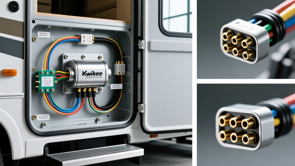
Understanding the Kwikee Step Wiring Diagram
Installing or replacing a motorized RV step requires a precise understanding of the control module's pinout and power requirements. Kwikee, now manufactured by Lippert Components, remains the industry standard for motorhome entry steps. Whether you are upgrading a Series 28, 32, or 42 step assembly, utilizing the correct Kwikee step wiring diagram is critical to prevent motor burnout, control module failure, or catastrophic highway deployment.
Modern Kwikee steps utilize a 6-pin weather-pack pigtail, while older legacy models may use a 4-pin configuration. This guide focuses on the modern 6-pin Lippert/Kwikee control module wiring standard, detailing exact wire colors, AWG requirements, and chassis integration protocols.
6-Pin Kwikee Pigtail Pinout and Specifications
The control module acts as the brain of the step assembly, managing motor polarity, step-light activation, and safety interlocks. Below is the definitive wiring chart for the 6-pin harness.
| Wire Color | Function | Recommended AWG | Connection Point |
|---|---|---|---|
| Red | 12V+ Main Power | 10 AWG | House Battery Bank (+) |
| Black | Main Chassis Ground | 10 AWG | Steel Chassis Frame |
| White | Step Light (12V+) | 14 AWG | RV Exterior Lighting Circuit |
| Yellow | Ignition Override (12V+) | 14 AWG | Ignition Switch (Run/On) |
| Brown | Door Switch Signal | 14 AWG | Magnetic Reed Switch |
| Green | Step Light Ground | 14 AWG | Chassis Ground / Light Fixture |
Pre-Installation: Wire Sizing and Fusing Protocols
DC electric motors experience a massive inrush current upon startup—often 3 to 5 times their continuous running amperage. A Kwikee step motor typically draws 10 to 15 amps during operation, but inrush can spike to 45 amps for a fraction of a second. If your wiring is undersized, voltage drop will cause the control module to reset or the motor to overheat.
- Main Power and Ground (Red/Black): You must use a minimum of 10 AWG stranded copper wire. Ensure the wire meets SAE J1128 standards for low-tension primary cable, which dictates strict insulation thickness and temperature resistance ratings up to 125°C.
- Signal Wires (White, Yellow, Brown, Green): 14 AWG stranded copper is sufficient, as these circuits carry minimal amperage (typically under 3 amps).
- Fusing: Install a 30A or 40A ATC/ATO blade fuse (or an equivalent marine-grade circuit breaker) on the Red 12V+ wire. This fuse must be located within 18 inches of the house battery positive terminal to protect the entire wire run from short circuits.
Step-by-Step Wiring Installation Guide
Follow this sequence to ensure a safe, RVIA-compliant installation that prevents moisture intrusion and voltage drop.
1. Route and Secure the Main Power Harness
Run the 10 AWG Red and Black wires from the step control module to the battery bay and chassis ground point. Secure the harness every 18 inches using UV-resistant zip ties or Adel clamps. Keep the wiring away from exhaust components, sharp frame edges, and moving suspension parts. Use split-loom tubing where the harness passes through the RV floor or frame crossmembers.
2. Establish a True Chassis Ground
The number one cause of erratic Kwikee step behavior is a poor ground. Do not ground the Black wire to the RV's aluminum skin, fiberglass subfloor, or bumper.
- Locate a heavy-gauge steel crossmember on the chassis frame near the step.
- Use a wire brush or sandpaper to remove all paint, rust, and undercoating down to bare, shiny metal.
- Attach a 10 AWG ring terminal (using a ratcheting crimper) to the Black wire.
- Bolt the ring terminal to the chassis using a Grade 8 bolt, a star washer (to bite into the metal), and a nyloc nut. Torque to 15-18 lb-ft.
- Apply a generous coating of dielectric grease over the terminal after tightening to prevent galvanic corrosion.
3. Wire the Ignition Override (Yellow Wire)
The Yellow wire is a critical safety interlock. When it receives 12V+, the control module locks the steps in the retracted position, overriding the door switch.
- Correct Connection: Splice the Yellow wire into a 12V+ source that is only hot when the chassis ignition is in the 'ON' or 'RUN' position.
- Common Mistake: Wiring this to a constant 12V+ source will prevent the steps from ever deploying. Wiring it to an 'Accessory' circuit (like the radio) may cause the steps to deploy while you are parked and listening to music, but retract when you turn the key to start the engine.
4. Connect the Magnetic Door Switch (Brown Wire)
The Brown wire completes the ground circuit to signal the control module to extend the steps. It connects to one side of the magnetic reed switch mounted on the entry door frame. The other side of the reed switch must be grounded to the chassis. When the door opens, the magnet moves away, the switch closes, and the ground signal tells the module to deploy the step.
Testing and Calibration
Before sealing up your wire runs, perform a full functional test:
- Turn the RV ignition OFF.
- Open the entry door. The step should deploy immediately, and the step light should illuminate (if the White wire is connected to a switched 12V+ source or the porch light circuit).
- Close the door. The step should retract.
- Turn the RV ignition ON.
- Open the door. The step must remain retracted. If it deploys, verify your Yellow wire is connected to a true ignition-switched 12V+ source.
Troubleshooting Common Kwikee Step Failures
If your step is malfunctioning, use this diagnostic tree before replacing the expensive control module or motor.
Symptom: Step Deploys but Will Not Retract
- Cause 1: Misaligned magnetic door switch. The gap between the magnet and the reed switch must be less than 1/2 inch. If the door has sagged on its hinges, the switch may not open when closed.
- Cause 2: Corroded ground. Check the Black wire chassis ground and the door switch ground.
Symptom: Motor Hums but Step Does Not Move
- Cause: Mechanical binding or stripped drive gear. The motor is receiving power, but the physical linkage is jammed. Disconnect the motor linkage and test the motor directly with a 12V jumper. If the motor spins freely, rebuild the step linkage and lubricate the pivot points with white lithium grease.
Symptom: Control Module LED Flashes Continuously
- Cause: The Lippert control module features a built-in diagnostic LED. A continuous rapid flash usually indicates a short circuit in the motor wiring or a seized motor drawing excessive amperage, causing the internal thermal breaker to trip. Check the motor brushes and inspect the wiring harness for chafing against the frame.
By strictly adhering to this Kwikee step wiring diagram and utilizing proper automotive-grade materials, you ensure your motorized steps will operate reliably for years, regardless of weather conditions or road vibrations.