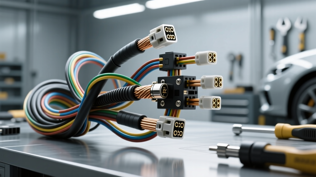
The Anatomy of Modern Automotive Wiring Looms
When addressing complex car wiring loom repairs, technicians must move beyond basic butt connectors and electrical tape. A modern automotive wiring harness is a highly engineered network of power distribution and high-speed data communication. Understanding the specific insulation chemistry and structural architecture of the loom is the first step in executing a repair that meets OEM durability standards. According to SAE J1128 specifications, automotive cables are categorized by temperature ratings and insulation thickness, which dictate how they must be handled during a repair.
- SXL (Cross-Linked Polyethylene): Standard for engine bay looms. Rated for 125°C. Highly resistant to abrasion and chemicals but requires higher heat to trigger adhesive heat shrink tubing.
- AVSS (Automotive Vinyl Thin Wall): Common in Japanese and Asian domestic market vehicles. Rated for 90°C. Features a very thin PVC insulation layer, requiring extreme care during stripping to avoid nicking the copper strands.
- GXL/TXL: Thin and extra-thin wall cross-linked insulations used in modern cabin and chassis looms to reduce overall vehicle weight and harness diameter.
Diagnostic Protocols for Loom Degradation
Before initiating car wiring loom repairs, the exact point of failure must be isolated. Stripping back meters of OEM loom tape to find a micro-short is destructive and time-consuming. Advanced diagnostics require specialized testing protocols.
Time Domain Reflectometry (TDR) and Micro-Shorts
For intermittent open circuits or high-resistance faults buried deep inside a harness, a Time Domain Reflectometer (TDR) sends a low-voltage pulse down the wire. By measuring the time it takes for the reflection to return, the TDR calculates the exact distance to the break or corrosion point, often within a margin of inches. This is critical for repairing looms that route through the firewall or under the carpet.
Diagnostic Decision Tree: Parasitic Draws & Loom Chafing
- Symptom: Battery drains overnight, but pulling the ECU fuse stops the draw.
- Verification: Perform a voltage drop test across the suspect circuit's fuse with the vehicle asleep. A reading above 0.005V indicates active current flow.
- Isolation: Inspect the loom where it passes through the bulkhead or near the strut tower. Look for 'loom bite'—where the harness rubs against sheet metal, wearing through the Tesa tape and SXL insulation.
- Fix: Repair the chafed wires using staggered open-barrel crimps and re-route the harness using a split-loom conduit and stand-off clips.
Advanced Repair Techniques: CAN Bus and Shielded Cables
The most critical aspect of modern car wiring loom repairs involves high-speed data networks and sensitive analog sensor circuits. Improper splicing in these circuits introduces Electromagnetic Interference (EMI) and signal reflection, leading to phantom diagnostic trouble codes (DTCs).
CAN Bus Twisted Pair Splicing Specifications
The Controller Area Network (CAN) bus relies on differential signaling over a twisted pair of wires (CAN-High and CAN-Low). The Bosch CAN Specification mandates strict physical layer parameters to maintain the characteristic impedance of 120 ohms. If a CAN wire breaks, you cannot simply untwist, splice, and re-tape. Altering the twist rate creates an impedance mismatch, causing signal reflections that corrupt data packets.
- Strip and Stagger: Strip back exactly 1.5 inches of insulation on both CAN-H and CAN-L. Stagger the splice points by at least 1 inch so the bulky repair nodes do not sit adjacent to one another.
- Maintain the Twist: OEM CAN bus cables typically feature 33 twists per meter. When re-joining the wires, you must manually twist the repaired section at this exact rate before applying heat shrink.
- Adhesive Heat Shrink: Use dual-wall, adhesive-lined polyolefin heat shrink with a 3:1 or 4:1 shrink ratio. The inner thermoplastic layer must melt and flow into the wire strands to create a moisture-proof environmental seal.
Shielded Sensor Cable Repairs
Sensors like the Crankshaft Position (CKP) sensor, Knock Sensors, and Oxygen (O2) sensors utilize shielded cables to protect low-voltage analog signals from the intense EMI generated by ignition coils and fuel injectors. The shield consists of a braided copper mesh or a spiral wrap, accompanied by an uninsulated 'drain wire'.
When repairing a shielded cable, the braided shield must be re-established over the splice point. The drain wire must be connected to the shield and grounded at one end only (typically the ECU side). Grounding both ends creates a ground loop, turning the shield into an antenna that amplifies alternator whine and ignition noise directly into the sensor signal wire.
Splicing Methodologies: Crimping vs. Soldering vs. Ultrasonic
There is a persistent myth in the automotive aftermarket that soldering is the gold standard for wire repairs. In high-vibration environments like an engine bay, soldering is actually detrimental. Solder wicks into the copper strands under the insulation via capillary action, creating a rigid stress concentration point. Over time, engine harmonics cause the wire to fatigue and snap exactly at the edge of the solder joint.
| Splicing Method | Best Application | Pros | Cons |
|---|---|---|---|
| Open Barrel Crimp (U-Crimp) | General loom repairs, power circuits | Cold weld, maintains wire flexibility, OEM standard | Requires specific ratcheting crimpers for proper pull-out force |
| Soldering | Stationary interior connections, audio | Low electrical resistance, cheap | Wicking causes stress fractures, melts XLP insulation |
| Ultrasonic Welding | EV High-Voltage looms, BMS harnesses | Zero heat damage, lowest resistance, molecular bond | Requires expensive specialized equipment |
For standard car wiring loom repairs, the TE Connectivity Automotive Harness Guidelines recommend using open-barrel, ratcheting crimpers. A proper crimp on a 20 AWG wire should withstand a pull-out force exceeding 15 lbs without the wire slipping from the terminal.
Loom Splitting, Environmental Sealing, and Re-Wrapping
Once the internal wire repairs are complete, the harness must be re-sealed and wrapped to OEM specifications. Using generic vinyl electrical tape is unacceptable; it unravels under high under-hood temperatures and leaves a corrosive adhesive residue.
Step-by-Step Harness Re-Wrapping Protocol
- Clean the Harness: Wipe down the existing loom with isopropyl alcohol to remove oil, grease, and old adhesive.
- Apply Corrugated Loom (If Required): For areas exposed to road debris or moving components (e.g., near the cooling fan or steering column), slide the repaired section into split corrugated tubing.
- Select the Correct Tape:
- Tesa 51036 (PET Fleece): Rated for 150°C. Use for engine bay harnesses. Highly resistant to heat and chemicals.
- Tesa 51608 (PET Fleece): Rated for 105°C. Use for interior cabin harnesses. Provides excellent abrasion resistance and prevents rattling against plastic trim.
- Wrapping Technique: Wrap the tape in a continuous spiral. For straight runs, maintain a 25% overlap. For harness bends and breakouts (where wires split off to a connector), increase the overlap to 50% and secure the end with a specialized harness tie, not a standard zip-tie which can cut into the insulation.
Connector Pin Extraction and Cavity Plugs
Often, the failure in a wiring loom occurs at the connector interface due to fretting corrosion or terminal tension loss. When replacing a pin, you must use the correct extraction tool for the specific connector family. For example, TE Superseal 1.5 connectors require a dual-prong extraction tool to depress the primary and secondary locking lances simultaneously. Deutsch DT series connectors require a specialized wedge removal tool to release the internal retention wedges.
Furthermore, any unused cavities in a repaired connector must be filled with silicone cavity plugs. This prevents moisture ingress and ensures the connector housing maintains its structural rigidity and environmental IP67/IP69K sealing rating. Neglecting cavity plugs is a leading cause of premature connector failure following a loom repair.
Summary of Best Practices
Executing professional-grade car wiring loom repairs requires a deep understanding of signal integrity, material science, and environmental sealing. By adhering to SAE cable standards, maintaining CAN bus twist rates, utilizing open-barrel crimping over soldering, and re-wrapping with temperature-rated PET fleece tapes, technicians can restore a damaged harness to factory reliability. Never compromise on the microscopic details of a wiring repair; the long-term electrical health of the vehicle depends entirely on the precision of the technician's methodology.