Introduction to Fuel Level Circuit Architecture
Understanding how to wire a fuel gauge in a custom, restomod, or heavily modified EFI vehicle requires moving beyond simple plug-and-play assumptions. A fuel level circuit is fundamentally an analog voltage divider network. The instrument cluster or standalone gauge measures the voltage drop across a variable resistor (the sending unit) located inside the fuel tank. While modern OEMs have largely transitioned to CAN-bus digital messaging for instrument clusters, the analog resistive sender remains the gold standard for aftermarket gauges, standalone EFI integrations, and classic car restorations.
In this advanced technical deep dive, we will dissect the electrical architecture of fuel level circuits. We will cover sender resistance profiling, Instrument Voltage Regulator (IVR) pulse-width modulation, wire gauge selection based on SAE J1128 Low Tension Primary Cable Standards, and the precise crimping methodologies required to ensure terminal retention in harsh under-chassis environments.
Sender Resistance Profiles and Gauge Matching
The most common failure point when wiring an aftermarket fuel gauge is a mismatch between the gauge's internal calibration and the fuel tank sender's resistance sweep. If you connect a 0-90 ohm GM-style sender to a gauge calibrated for a 240-33 ohm Stewart-Warner sweep, the needle will peg past 'Full' and read erratically. You must verify the empty and full resistance values using a digital multimeter (DMM) before routing any wires.
| Manufacturer / Standard | Empty Resistance (Ohms) | Full Resistance (Ohms) | Typical Application |
|---|---|---|---|
| Stewart-Warner (SW) | 240 Ω | 33 Ω | Most Aftermarket Gauges, Chrysler (Late) |
| General Motors (GM) | 0 Ω | 90 Ω | GM Trucks & Cars (1965-1996) |
| Ford | 10 Ω | 180 Ω | Ford Vehicles (1987-1996) |
| Chrysler (Early) | 73 Ω | 10 Ω | Mopar A/B/E Body (1960-1986) |
| VDO / European | 10 Ω | 180 Ω | BMW, VW, Porsche, Marine |
The Role of the Instrument Voltage Regulator (IVR)
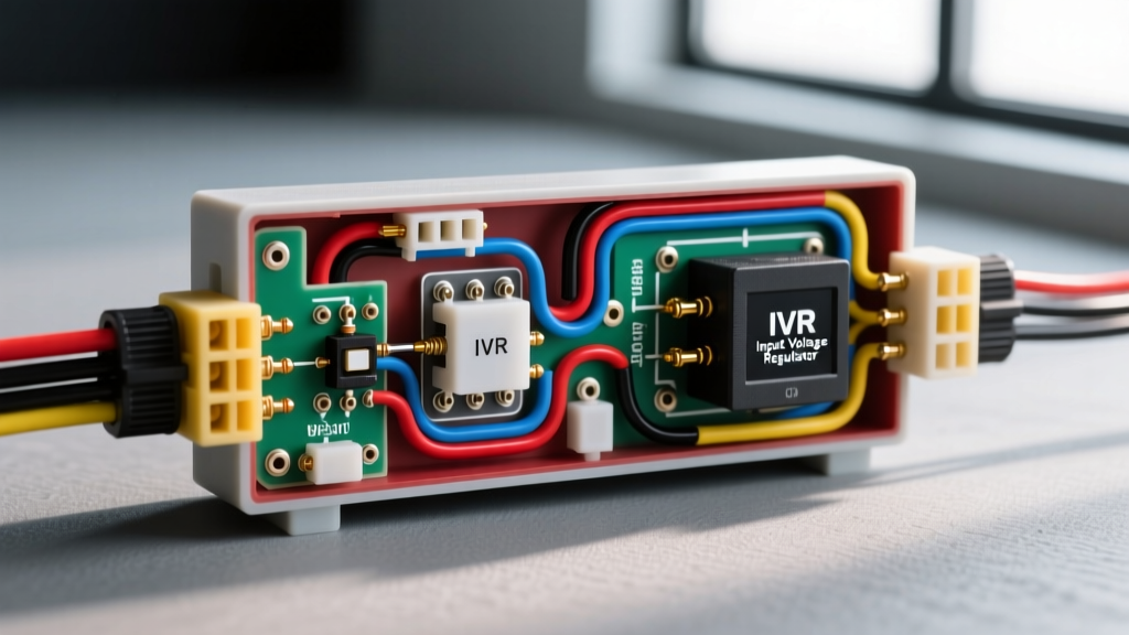
Analog thermal-style fuel gauges do not read system voltage; they read a regulated reference voltage, typically 5.0V. Older vehicles used a mechanical bimetallic strip IVR that physically pulsed the 12V battery voltage down to an average of 5V. This mechanical switching introduces massive electromagnetic interference (EMI) and needle flutter. When wiring a modern aftermarket fuel gauge, you must use a solid-state, fully electronic IVR. Solid-state IVRs provide a clean, ripple-free 5.0V reference, ensuring the needle sweep is smooth and immune to alternator whine or voltage drops during engine cranking.
Wiring Specifications: AWG, Insulation, and Routing
The signal wire traveling from the tank sender to the dashboard gauge carries virtually zero current (usually less than 150mA). However, because it routes along the vehicle's chassis alongside high-current fuel pump feeds and ignition harnesses, it is highly susceptible to capacitive coupling and inductive noise. Selecting the correct wire and insulation is critical.
Wire Gauge and Insulation Types
- Signal Wire: 18 AWG TXL (Thin-wall Cross-linked). TXL insulation is highly resistant to heat, chemicals, and abrasion, and its thin profile allows for tight bend radii behind the dashboard.
- Sender Ground Wire: 18 AWG TXL. Must be routed all the way back to the engine block or battery negative. Never rely on the fuel tank strap or chassis rust for the sender ground.
- Fuel Pump Power (If integrated): 12 AWG or 10 AWG SXL, depending on the pump's amperage draw (e.g., a Walbro 450 requires 10 AWG).
Terminal Crimping and Connector Selection
For the dash-side connection, the industry standard is the Aptiv (formerly Delphi) Metri-Pack 150 series. These connectors feature a primary locking lance on the terminal and a secondary Terminal Position Assurance (TPA) comb to prevent back-out from vibration. For the fuel tank sender pigtail, a Deutsch DT or Flange-Mount HD10 series connector is preferred due to its IP68 waterproof sealing and silicone grommets.
When crimping Metri-Pack open-barrel terminals, you must use a ratcheting crimper designed for F-crimp (open barrel) profiles. The crimp die must feature two distinct stages: the wire crimp (which folds the metal wings tightly into the copper strands for a cold-weld gas-tight connection) and the insulation crimp (which secures the wire jacket to provide strain relief). A proper crimp will pass a 15 lb pull-test without the wire slipping from the terminal barrel.
Step-by-Step Advanced Wiring Procedure
The following procedure outlines how to wire a fuel gauge in an EFI restomod application, utilizing a 4-pin tank connector that integrates both the high-current fuel pump and the low-current analog sender.
Step 1: Establish the Dedicated Analog Ground
- Locate the sender's ground pin on the tank flange (typically Pin D on a 4-pin OEM-style pigtail).
- Crimp an 18 AWG TXL wire using a sealed Metri-Pack terminal.
- Route this ground wire along the chassis, securing it every 12 inches with adhesive-lined heat shrink and zip ties.
- Terminate the ground at a dedicated, clean bare-metal stud on the engine block or directly at the battery negative terminal. Crucial: Do not share this ground with the fuel pump ground. The fuel pump draws 10-15 amps; sharing the ground wire will introduce a voltage drop that will artificially shift the sender's resistance reading, causing the gauge to read lower than the actual fuel level when the pump cycles on.
Step 2: Routing the Sender Signal Wire
- Identify the sender signal pin (typically Pin C).
- Route the 18 AWG signal wire through the interior cabin, keeping it at least 4 inches away from the fuel pump +12V feed, ignition coil wires, and distributor harnesses to prevent inductive cross-talk.
- At the dashboard, connect the signal wire to the 'S' or 'Sender' terminal on the back of the fuel gauge.
Step 3: Power and IVR Integration
- Run a 14 AWG wire from a switched 12V ignition source (e.g., the ignition switch 'RUN' terminal) to the input side of a solid-state 5V Instrument Voltage Regulator.
- Connect the 5V output of the IVR to the 'I' or 'Ignition' terminal on the fuel gauge.
- Ground the IVR casing to a clean dashboard metal framing point using a star washer to bite through paint and primer.
Troubleshooting Signal Noise and Erratic Needle Sweep
Even with perfect wire routing, analog fuel gauges can suffer from erratic behavior. Use this advanced diagnostic decision tree to isolate the fault based on Auto Meter Technical Installation Guidelines and field diagnostics.
- Symptom: Needle sweeps full, then drops to empty repeatedly.
- Cause: Failing mechanical IVR or loose IVR ground.
- Fix: Replace with a solid-state electronic IVR. Verify IVR case ground continuity to the battery negative (must be less than 0.05 ohms).
- Symptom: Gauge reads accurately at 'Full' but reads 1/4 tank when 'Empty'.
- Cause: High resistance in the sender ground circuit (voltage divider offset).
- Fix: Perform a voltage drop test on the sender ground wire with the ignition ON. If you read more than 0.1V across the ground wire, clean the chassis ground point or increase the wire gauge to 16 AWG.
- Symptom: Needle vibrates or 'dances' in sync with engine RPM or fuel pump whine.
- Cause: Electromagnetic Interference (EMI) coupling into the signal wire, or PWM noise from a modern fuel pump controller.
- Fix: Install a 100µF to 470µF electrolytic capacitor across the gauge's 'I' (5V reference) and 'S' (Signal) terminals. The capacitor acts as a low-pass filter, absorbing high-frequency AC noise while allowing the slow-changing DC resistance signal to pass through, resulting in a perfectly steady needle.
- Symptom: Gauge reads 'Empty' regardless of fuel level.
- Cause: Signal wire shorted to ground, or sender float arm detached inside the tank.
- Fix: Disconnect the sender pigtail at the tank. Measure resistance between the signal pin and the ground pin on the tank flange. If the resistance reads 0 ohms, the internal sender wiper is shorted or the float has sunk. If resistance sweeps smoothly (e.g., 240 to 33 ohms) while manually moving the float arm, the short is in the chassis wiring harness.
Summary of Best Practices
Learning how to wire a fuel gauge correctly is an exercise in managing resistance and mitigating noise. By matching the sender's ohm scale to the gauge, utilizing TXL wire, executing gas-tight open-barrel crimps, and isolating the analog ground from high-current EFI circuits, you guarantee a reliable, flutter-free fuel level reading for the life of the vehicle.