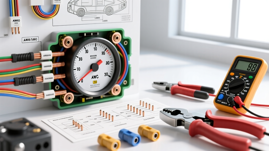
The True Cost of Wiring an Aftermarket RPM Gauge
When enthusiasts set out to learn how to wire a RPM gauge, the focus is usually on finding the tachometer signal source. However, the hidden costs of a failed installation—ranging from parasitic battery draws to frying a $1,200 Powertrain Control Module (PCM) via a back-probed pin short—far exceed the price of the gauge itself. A professional-grade electrical installation requires specific wire gauges, ratcheting crimp tools, and proper termination techniques. This cost and tool requirements analysis breaks down exactly what you need to execute a flawless, OEM-tier aftermarket tachometer installation, ensuring your signal is clean and your vehicle's electrical system remains protected.
Tool & Material Cost Analysis Matrix
Using non-ratcheting crimpers or generic electrical tape leads to high-resistance connections that degrade underhood temperatures. Below is a comparative analysis of budget versus professional tool investments required for gauge wiring.
| Tool Category | Budget Option (Risk Level) | Professional Option (Recommended) | Cost Difference | Long-Term Value & E-E-A-T Justification |
|---|---|---|---|---|
| Wire Crimper | Generic stamped steel pliers ($12) | Knipex or TE Connectivity Ratcheting Crimper ($85) | +$73 | Ratcheting tools ensure the terminal barrel is crushed to the exact wire AWG specification before releasing, preventing pull-out failures. |
| Wire Stripper | Standard manual strippers ($8) | Knoweasy or Klein 18-22 AWG Precision Strippers ($25) | +$17 | Prevents nicking the copper strands, which reduces current capacity and creates a fatigue point under engine vibration. |
| Multimeter | Free auto parts store tester ($0) | Fluke 87V or Power Probe IV ($250+) | +$250 | Essential for verifying the 5V square-wave tach signal and checking for continuity without back-probing and damaging PCM seals. |
| Tach Adapter | Inductive coil clamp ($15) | Dakota Digital SGX-100 CAN-bus Decoder ($89) | +$74 | Modern DIS/COP ignition systems lack a traditional coil-negative signal. CAN-bus decoders read OBD2 data for a flawless needle sweep. |
Wire, Terminal, and Connector Specifications
Automotive environments demand high-temperature, chemical-resistant materials. According to SAE J1128 standards for Low Tension Primary Cable, standard PVC wire melts and shorts under exhaust heat. For routing an RPM gauge signal from the engine bay to the cabin, you must use 18 AWG TXL or GXL (Cross-Linked Polyethylene) wire. GXL wire features a thin, high-temp insulation wall that easily fits into tight Deutsch or AMP connector cavities.
For under-dash splices, abandon vinyl electrical tape. Use Nylon-Insulated Heat-Shrink Butt Connectors rated for 22-18 AWG. The internal brass barrel provides a gas-tight crimp, while the outer polyolefin tube shrinks and seals against moisture. For firewall pass-throughs, always utilize an existing rubber grommet. If drilling a new hole, install a chassis grommet to prevent the 18 AWG wire from shorting against bare sheet metal, which will instantly blow the gauge's internal fuse or damage the ECU.
How to Wire a RPM Gauge: Signal Source Identification
The most critical step in the installation is identifying the correct tachometer signal source. The signal type dictates whether you can wire the gauge directly or if a signal conditioner is required.
1. GM LS-Series V8 (1997-2013 Truck/SUV)
Gen III and Gen IV LS engines output a clean 5V square-wave tach signal directly from the PCM. You must locate the C1 Connector (Black) on the PCM. The tach signal is located at Pin 10 (Dark Green wire). Rather than piercing the wire insulation with a T-tap (which invites corrosion and signal degradation), use a proper Posi-Tap or, preferably, depin the connector, solder a pigtail, and repin using an OEM-style terminal.
2. Ford Modular & Coyote V8 (CAN-Bus Systems)
Modern Ford engines do not output a dedicated hardwired tach signal. The RPM data is broadcast exclusively over the High-Speed CAN-bus network (OBD2 Pins 6 and 14). To wire a traditional analog RPM gauge here, you must install a CAN-bus tach adapter (like the Dakota Digital SGX-100). The adapter intercepts the CAN data and generates a standard 12V square-wave pulse that the aftermarket gauge can read.
3. Classic GM HEI Distributors
For older V8s with an HEI distributor, the tach signal is a pulsing 12V square wave taken directly from the TACH terminal on the distributor cap. Note: If using an MSD 6AL ignition box, the signal must be pulled from the MSD's dedicated Tach Output terminal (White wire), not the coil negative, to prevent gauge damage from high-voltage spikes.
Standard 4-Pin Tachometer Wiring Execution
Most aftermarket gauges (Autometer, Stewart Warner, VDO) utilize a standard 4-pin terminal block. Below is the exact pinout and termination strategy.
| Pin / Terminal | Function | Wire Color (Standard) | AWG Size | Termination Point & Connector Type |
|---|---|---|---|---|
| Pin 1 | Switched 12V Power | Red | 18 AWG | Ignition switch fuse panel (via Add-A-Circuit fuse tap). Ring terminal to fuse tap. |
| Pin 2 | Signal Input | Green | 18 AWG | PCM Tach Pin, CAN-Adapter, or HEI Tach terminal. Heat-shrink butt splice. |
| Pin 3 | Ground | Black | 18 AWG | Clean, bare chassis metal. Star washer and #8 Ring Terminal. |
| Pin 4 | Lighting / Dimmer | White / Blue | 18 AWG | Headlight switch dimmer circuit (for synchronized gauge illumination). |
Routing, Grounding, and Signal Integrity
Signal integrity is paramount when wiring an RPM gauge. The tach signal wire (Green) is highly susceptible to Electromagnetic Interference (EMI) generated by alternators, ignition coils, and fuel injectors. Never route the tach signal wire parallel to ignition coil primary wires or alternator output cables. If crossing high-current cables is unavoidable, cross them at a strict 90-degree angle to minimize inductive coupling.
The ground circuit (Pin 3) is responsible for completing the internal logic board's reference voltage. A poor ground results in a bouncing needle or a gauge that reads exactly 500 RPM higher than actual engine speed. Strip the 18 AWG ground wire to exactly 5/16", crimp a nylon-insulated #8 ring terminal, and secure it to a bare metal chassis point using a star washer. Apply a thin layer of No-Ox-Id A-Special conductive grease to prevent galvanic corrosion over time. For deeper insights on OEM connector and grounding standards, refer to the Aptiv/Delphi Electrical Connector Repair Guidelines.
Troubleshooting Tachometer Signal Failure
If your gauge is powered and grounded but the needle remains dead or erratic, use the following diagnostic tree before replacing the gauge:
- Symptom: Needle bounces wildly at idle.
- Cause: EMI interference or incorrect cylinder setting.
- Fix: Verify the dip-switch or wire-loop setting on the back of the gauge matches the engine (e.g., 4, 6, or 8 cylinders). If correct, route the signal wire away from spark plug wires.
- Symptom: Needle reads exactly half of actual RPM.
- Cause: Gauge is set to 4-cylinder mode on an 8-cylinder engine, or signal is pulled from a wasted-spark coil pack without a tach adapter.
- Fix: Adjust the cylinder selector switch to 8-CYL. If using a wasted-spark DIS, install a Dakota Digital SGI-5E signal interface to double the pulse frequency.
- Symptom: Gauge powers on, but needle never moves.
- Cause: No signal reaching Pin 2, or incompatible signal type (e.g., feeding a 5V logic signal into a 12V inductive gauge).
- Fix: Connect an automotive oscilloscope or advanced multimeter to the signal wire. As detailed in the Pico Technology Tachometer Waveform Guide, a healthy PCM signal should show a crisp 0V to 5V (or 0V to 12V) square wave. If the waveform is present at the PCM but missing at the gauge, repair the open circuit in your 18 AWG green wire.
By investing in the correct ratcheting crimpers, utilizing 18 AWG GXL wire, and respecting OEM pinout data, your RPM gauge installation will deliver accurate, jitter-free data for the life of the vehicle.