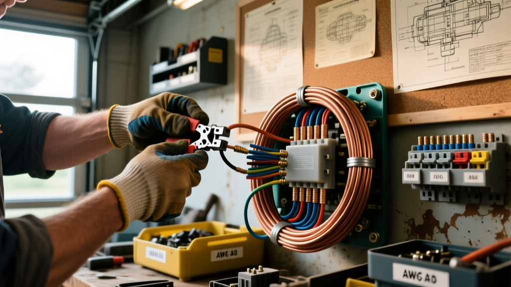
Project Overview: Modernizing the 1970 C10 Electrical System
When undertaking a complete harness overhaul on a classic vehicle, the methodologies championed by premier auto electrical repair Fredericksburg specialists emphasize moving away from brittle, 50-year-old PVC wires to modern cross-linked polyethylene (XLPE) insulated cables. This upgrade project focuses on a 1970 Chevrolet C10 truck, replacing the degraded factory lighting and ignition circuits with a modern, relay-driven architecture. Classic trucks are notorious for routing full headlight current through the dashboard switch and a single bulkhead connector. This outdated design leads to severe voltage drop, melted firewall plugs, and dim halogen output.
By integrating standard 5-pin ISO micro relays and upgrading the main power feeds to 10 AWG GXL wire, we can restore optimal voltage at the bulb and eliminate the fire hazard associated with aging, high-resistance copper. This guide details the exact wire specifications, crimping protocols, and relay pinouts required to execute a professional-grade modification.
Wire Gauge Selection and Voltage Drop Mitigation
Upgrading a classic truck requires strict adherence to wire gauge sizing to prevent thermal runaway. According to SAE J1128 standards for low-tension primary cables, GXL (General Cross-Linked) wire offers superior abrasion resistance and a thinner insulation wall compared to standard PVC, allowing for tighter routing in the engine bay while handling higher thermal loads.
When calculating voltage drop, we use the formula: VD = (2 x L x R x I) / 1000, where L is the one-way wire length in feet, R is the resistance per 1000 feet, and I is the current in amps. For a 15-foot run to the headlights drawing 12 amps on a 14 AWG wire, the voltage drop is nearly 1.5 volts—enough to noticeably dim the bulbs. Upgrading to 10 AWG reduces this drop to an imperceptible 0.36 volts.
| AWG Size | Max Amps (Chassis Wiring) | Resistance (Ω / 1000ft) | Primary Upgrade Application |
|---|---|---|---|
| 10 AWG | 30A | 0.9989 Ω | Headlight main feeds, Fuel pump, Starter solenoid |
| 12 AWG | 20A | 1.588 Ω | Tail lights, Horn, HVAC blower motor |
| 14 AWG | 15A | 2.525 Ω | Relay trigger circuits, Dash illumination, Wipers |
| 16 AWG | 10A | 4.016 Ω | Sensors, ECU signals, LED marker lights |
Upgrading the Headlight Circuit with ISO Relays
The core of this modification involves bypassing the factory headlight switch for the high-current load. The OEM switch will now only carry the low-current trigger signal (approx. 0.5 amps) to activate the relays. We utilize two standard 5-pin ISO micro relays—one for the low beams and one for the high beams. As referenced in Littelfuse automotive relay documentation, proper pin mapping is critical to prevent shorting the trigger circuit to the high-amperage battery feed.
Standard 5-Pin ISO Relay Pinout Configuration
| Pin Number | Function | Wire Gauge & Color Code | Routing Destination |
|---|---|---|---|
| Pin 30 | 12V+ Battery Input (Constant) | 10 AWG Red | Fused directly to battery positive terminal |
| Pin 87 | Normally Open (NO) Output | 10 AWG Red (w/ Black tracer) | To headlight bulb positive terminal |
| Pin 85 | Ground / Trigger Input | 14 AWG Black | Local chassis ground via ring terminal |
| Pin 86 | Switched 12V+ Trigger | 14 AWG White | Spliced into OEM headlight switch output |
| Pin 87a | Normally Closed (NC) | N/A | Cut flush and sealed with heat shrink |
Termination: Weather-Pack Crimping and Heat Shrink
When diagnosing complex voltage drops, the diagnostic trees utilized by top auto electrical repair Fredericksburg technicians heavily scrutinize terminal crimps. A poorly executed crimp introduces micro-gaps where oxygen enters, leading to copper oxidation and increased resistance over time. For this project, we use Delphi (Aptiv) Weather-Pack connectors due to their silicone secondary locks and robust cavity seals.
Open-Barrel vs. Closed-Barrel Crimping
Modern OEM harnesses predominantly use open-barrel terminals, which require a specific F-crimp or B-crimp profile. Using a ratcheting crimper like the HX-48B or an IWISS SN-48B ensures the terminal wings fold inward symmetrically to grip the conductor strands, while the secondary insulation tabs secure the GXL jacket. The insulation grip must withstand a pull-out force exceeding 40 lbs, while the wire grip must hold over 70 lbs of tensile stress without the copper slipping.
- Strip the Wire: Remove exactly 5mm of insulation for a 10 AWG Weather-Pack terminal. Do not nick the outer strands of the copper.
- Position the Terminal: Insert the open-barrel terminal into the correct die cavity of the ratcheting crimper.
- Align the Conductor: Slide the bare copper into the wire grip until it is flush with the front edge of the terminal. Ensure no loose strands are splayed outward.
- Engage the Insulation Grip: The yellow GXL jacket must sit fully inside the rear insulation tabs. If the jacket is too short, the terminal will cut into the bare copper during vibration, causing a stress fracture.
- Crimp and Inspect: Squeeze the ratchet until it releases. Inspect the crimp; you should see a slight bell-mouth at the front of the wire grip, indicating the copper was pushed fully home.
The Grounding Hierarchy and Chassis Preparation
A common failure point in DIY upgrades is poor chassis grounding. Electrons require a zero-resistance path back to the alternator and battery negative terminal. Paint, powder coating, and rust act as insulators. Our protocol requires using a 10 AWG tin-plated copper ring terminal (sized for a #10 or 1/4-inch stud) secured with a stainless steel internal-tooth star washer.
The star washer bites through the factory e-coat and primer to establish bare metal-to-metal contact. After torquing the bolt to 15 lb-ft, we coat the entire termination in conductive copper grease or heavy-duty dielectric grease. This prevents galvanic corrosion, a frequent issue noted in professional service bays when dealing with mixed-metal contacts in humid environments. For the headlight upgrade, we run dedicated 10 AWG ground wires from the bulb housing directly to a centralized ground bus bar mounted on the inner fender, rather than relying on the rusty front radiator support.
Circuit Protection: Sizing ATC Fuses
Every new 10 AWG feed from the battery must be protected within 18 inches of the positive terminal. We utilize standard ATC (Automotive Blade) fuse holders. Sizing the fuse correctly is critical; it must protect the wire, not just the load. Since 10 AWG wire is rated for 30 amps in chassis wiring applications, and our headlight circuit draws a maximum of 14 amps (including inrush current), a 20-Amp ATC fuse is the optimal choice. This provides a 30% safety buffer above the operating current while remaining well below the thermal limit of the wire. For detailed harness routing diagrams and bulkhead pass-through techniques, refer to the Painless Performance classic truck wiring manuals, which serve as the industry benchmark for aftermarket harness integration.
Testing and Validation Protocol
Once the relays are mounted in a sealed fuse block under the hood and all crimps are secured with dual-wall adhesive-lined heat shrink, the system must be validated. Using a digital multimeter, measure the voltage at the battery with the engine running (should be 13.8V - 14.4V). Turn on the upgraded headlights and measure the voltage directly at the bulb socket. A properly executed upgrade will show no more than a 0.2V to 0.3V difference between the alternator output and the bulb socket, confirming that the 10 AWG wire and ISO relays have successfully eliminated the factory voltage drop.