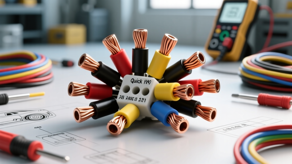
Technical Overview: Insulation Displacement Connectors (IDCs)
The quick splice wire connector, commonly referred to in the automotive aftermarket as a T-tap, Scotchlok, or vampire tap, is a specific class of Insulation Displacement Connector (IDC). Designed to bridge a secondary circuit to an existing primary wire without stripping the primary insulation, these connectors rely on a U-shaped metal channel (the blade) that cuts through the polymer insulation to make contact with the underlying copper strands. While they offer rapid deployment for accessory installations, their use in modern 12V automotive electrical systems requires a strict adherence to AWG specifications, current limitations, and environmental constraints to prevent catastrophic circuit failures.
AWG Compatibility and Electrical Specifications
Quick splice wire connectors are color-coded to match specific American Wire Gauge (AWG) ranges and their corresponding metric cross-sectional areas. Using a connector outside its designated AWG range results in either incomplete insulation penetration (yielding an open circuit) or excessive strand severing (creating a high-resistance bottleneck). Below is the standard technical specification chart for automotive-grade T-taps.
| Color Code | AWG Range | Metric (mm²) | Max Continuous Current | U-Channel Blade Width | Target Insulation OD |
|---|---|---|---|---|---|
| Red | 22 - 18 AWG | 0.35 - 0.82 mm² | 5 Amps | 0.025" (0.64mm) | 0.040" - 0.070" |
| Blue | 16 - 14 AWG | 1.31 - 2.08 mm² | 12 Amps | 0.035" (0.89mm) | 0.070" - 0.100" |
| Yellow | 12 - 10 AWG | 3.31 - 5.26 mm² | 25 Amps | 0.045" (1.14mm) | 0.100" - 0.145" |
Note: The "Max Continuous Current" rating is heavily derated compared to the bare wire capacity. A standard 12 AWG wire can safely carry 40A in free air, but a yellow quick splice wire connector introduces a localized resistance point that limits safe continuous draw to roughly 25A before thermal degradation of the nylon housing occurs.
The Physics of Failure: Strand Severing and Fretting
To understand the limitations of the quick splice wire connector, one must examine the mechanical interaction between the U-channel blade and stranded automotive copper. The blade is designed to push strands aside and wedge them into the narrow slot, creating a gas-tight cold weld. However, in real-world automotive applications, several failure modes dominate:
1. Strand Severing in Thin-Wall (TXL/GXL) Wire
Modern OEM automotive harnesses utilize TXL (Thin-wall) or GXL (General) cross-linked polyethylene insulation to save weight and reduce harness diameter. Standard quick splice connectors were originally engineered for thicker, standard PVC insulation. When a T-tap is crimped onto a TXL wire, the lack of insulation cushion often causes the U-channel blade to slice completely through the copper strands rather than wedging them. This reduces the effective cross-sectional area of the wire at the splice point, increasing resistance and generating localized heat under load.
2. Vibration-Induced Fretting Corrosion
According to SAE J1128 standards for low-tension primary cable, automotive wiring is subjected to continuous high-frequency vibration. The mechanical grip of a quick splice is solely dependent on the deformation of the insulation and the friction of the copper strands against the brass or nickel-plated blade. Over time, vibration causes micro-movements (fretting) between the blade and the copper. This breaks down the oxide layer, leading to galvanic corrosion, which manifests as a progressive voltage drop and eventual open circuit.
3. Moisture Wicking and Capillary Action
Because the primary insulation is punctured and rarely sealed perfectly by the plastic snap-cap, moisture can infiltrate the splice. More dangerously, if the connector is used in an engine bay environment, capillary action can draw water and road salts under the wire insulation, corroding the copper strands inches away from the splice point, making the damage invisible during standard visual inspections.
Automotive Application Matrix: Acceptable vs. Prohibited Uses
As an automotive electrical standard, the IPC/WHMA-A-620 specification generally rejects IDCs for high-reliability harness assemblies. However, in aftermarket diagnostics and accessory integration, they have a narrow band of acceptable utility.
Prohibited: High-Current and Under-Hood Circuits
- Alternator Sense Wires & Main Power: Never use a quick splice wire connector on 10 AWG or 8 AWG charging circuits. The thermal cycling will melt the plastic housing.
- Fuel Pump Relays & Injectors: The voltage drop introduced by the U-channel blade can alter the pulse-width modulation (PWM) signals or starve high-pressure fuel pumps of required amperage, triggering lean codes (e.g., P0171).
- Under-Hood/Exterior Splices: Environmental exposure guarantees corrosion within 12 to 18 months.
Prohibited: CAN-BUS and High-Speed Data Networks
Tapping into HS-CAN (High-Speed Controller Area Network) or MS-CAN twisted pair networks using T-taps is strictly prohibited. Data networks rely on precise characteristic impedance (typically 120 ohms). A quick splice wire connector introduces an unterminated stub and alters the physical geometry of the twisted pair, causing signal reflection, data packet collisions, and cascading U-code communication faults across multiple vehicle modules.
Acceptable: Interior Low-Current Accessory Taps
The only defensible use case for quick splice wire connectors in automotive repair is for temporary diagnostics or interior, low-current accessory installations where the harness is protected from moisture and extreme heat. Examples include:
- Tapping a 20 AWG BCM (Body Control Module) output for LED footwell lighting (Draw: < 1 Amp).
- Triggering a relay coil from an existing 18 AWG interior dome light circuit.
- Temporary back-probing alternative for monitoring a 5V reference signal during OBD-II scope diagnostics (provided the tap is removed and sealed afterward).
Installation Protocols and Tooling Requirements
If a quick splice wire connector must be utilized within its acceptable parameters, proper installation tooling is mandatory. Using slip-joint pliers to crush the connector is a primary cause of immediate failure, as it deforms the U-channel, preventing it from cleanly piercing the insulation.
- Wire Selection: Verify the primary wire gauge using a digital caliper to measure the copper diameter, not just the insulation thickness, to ensure correct AWG matching.
- Tooling: Use a dedicated ratcheting IDC crimping tool. The tool must apply even, parallel pressure across the metal cap to force the U-blade through the insulation uniformly.
- Secondary Wire Termination: The female spade or butt-crimp side of the T-tap must be crimped using a standard ratcheting terminal crimper, followed by the application of adhesive-lined heat shrink tubing over the secondary wire entry point to provide strain relief.
- Sealing: Wrap the entire quick splice assembly in high-temperature silicone amalgamating tape or apply a dielectric grease-filled heat shrink boot to block ambient cabin moisture.
Diagnostic Troubleshooting: The Millivolt Drop Test
When diagnosing a circuit suspected of having a failing quick splice wire connector, visual inspection is insufficient. The internal copper may be completely corroded while the external nylon housing appears pristine. Technicians must perform a dynamic voltage drop test.
- Set the digital multimeter (DMM) to the DC Millivolt (mV) scale.
- With the circuit under its normal operating load, place the red probe on the primary wire upstream of the splice, and the black probe on the secondary wire downstream of the splice.
- A healthy quick splice connection should exhibit a voltage drop of less than 10mV to 20mV per ampere of current flow.
- If the DMM reads a drop exceeding 100mV (0.1V) on a low-current 2A circuit, the U-channel blade has succumbed to fretting corrosion or strand severing, and the connector must be cut out and replaced with a solder-sealed solder sleeve or a proper OEM terminal pin insertion.