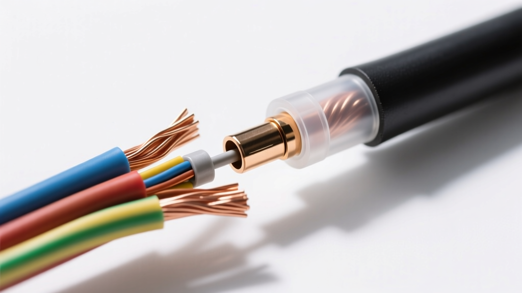
The Physics of Moisture Ingress and Galvanic Corrosion
In automotive and marine electrical systems, a standard wire splice is a primary failure point. When moisture penetrates a traditional PVC or nylon butt connector, capillary action draws water deep into the copper stranding. This initiates galvanic corrosion, converting the highly conductive copper into cuprous oxide—a semiconductor that introduces severe voltage drop and high resistance. For modern multiplexed networks like CAN-FD or FlexRay, even minor corrosion alters the characteristic 120-ohm impedance, causing signal reflection, packet loss, and ghost diagnostic trouble codes (DTCs).
Creating a true water proof wire splice requires defeating capillary action through a combination of mechanical compression and hermetic chemical sealing. According to the IPC-WHMA-A-620 standard for cable and wire harness assemblies, environmental sealing is not achieved by the outer jacket alone, but by the internal displacement of air and moisture via a thermoplastic adhesive barrier.
Material Science: Dual-Wall Polyolefin vs. Solder Seal Sleeves
When engineering a water proof wire splice, technicians generally choose between dual-wall adhesive heat shrink and solder seal sleeves. Understanding the material science of both is critical for high-vibration, wet-zone applications (e.g., wheel speed sensors, under-hood fuel injector harnesses, or marine bilge pumps).
Dual-Wall Adhesive Heat Shrink (Polyolefin/EVA)
Dual-wall tubing features an outer jacket of cross-linked polyolefin and an inner lining of Ethylene Vinyl Acetate (EVA) or polyamide hot-melt adhesive. The outer jacket is irradiated to create a 'memory effect,' allowing it to shrink at approximately 120°C (248°F). The inner EVA adhesive melts at a lower threshold of roughly 80°C (176°F). As the polyolefin shrinks, it exerts radial pressure, forcing the molten adhesive into the interstitial voids of the copper strands and the insulation jacket, creating a hydrophobic, IP67-rated seal.
Solder Seal Sleeves (Sn60/Pb40 or RoHS Sn99.3/Cu0.7)
Solder sleeves utilize a thermoplastic outer shell with pre-formed rings of flux-core solder and hot-melt adhesive. While excellent for low-vibration, low-current sensor circuits, they are generally discouraged for high-vibration automotive power circuits. Solder creates a rigid metallurgical bond that lacks the fatigue resistance of a mechanical crimp. Under the thermal cycling and vibration profiles defined in SAE J1455, rigid solder joints on 16 AWG or larger wires are prone to work-hardening and catastrophic fracture.
AWG Sizing, Strip Lengths, and Crimp Specifications
A water proof wire splice is only as reliable as the mechanical bond beneath the seal. For high-reliability harness repair, use a closed-barrel (F-type) crimp rather than an open-barrel (U-type) stamping. The F-crimp completely encapsulates the wire, preventing the adhesive from pooling at the bottom of the crimp and leaving voids at the top.
| Wire Gauge (AWG) | Cross-Section (mm²) | Crimp Die Color | Strip Length | Heat Shrink OD (Pre-Shrink) | Crimp Force (Approx) |
|---|---|---|---|---|---|
| 18 AWG | 0.82 mm² | Red | 1/4' (6.4mm) | 6.0 mm | 1.5 kN |
| 16 AWG | 1.31 mm² | Blue | 5/16' (8.0mm) | 8.0 mm | 2.5 kN |
| 14 AWG | 2.08 mm² | Blue | 3/8' (9.5mm) | 10.0 mm | 3.5 kN |
| 12 AWG | 3.31 mm² | Yellow | 7/16' (11.1mm) | 12.0 mm | 5.0 kN |
| 10 AWG | 5.26 mm² | Yellow | 1/2' (12.7mm) | 15.0 mm | 8.0 kN |
Step-by-Step Execution for IP67-Rated Splices
Achieving a factory-grade water proof wire splice requires strict adherence to thermal profiling and mechanical preparation. Follow this procedure for dual-wall adhesive splicing in under-hood or chassis environments.
- Preparation and Stripping: Use a precision wire stripper to avoid nicking the copper strands. Nicked strands create stress risers that will snap under engine vibration. Strip exactly to the lengths specified in the table above.
- Staggering (For Multi-Wire Harnesses): If splicing a multi-conductor harness (e.g., a 4-wire O2 sensor), stagger the inline splices by at least 1 inch. This prevents a bulky, rigid cluster that can fatigue and break under chassis flex.
- The Mechanical Crimp: Insert the wires into a seamless, copper-alloy butt connector. Use a ratcheting crimp tool with the correct AWG die. The crimp must pass a pull-test; the wire insulation should tear before the copper pulls out of the barrel.
- Cleaning: Wipe the wire insulation and the crimp barrel with isopropyl alcohol (IPA). Silicone dielectric grease or finger oils on the PVC insulation will prevent the hot-melt adhesive from bonding to the jacket.
- Thermal Application: Slide the dual-wall heat shrink over the splice. Ensure the tubing overlaps the wire insulation by at least 3/4 inch (19mm) on both sides. Apply heat using a calibrated hot air gun set to 250°C (480°F). Never use an open flame lighter, which carbonizes the polyolefin and destroys its dielectric strength.
- Adhesive Purge Verification: Heat from the center outward. The IPC-WHMA-A-620 standard dictates that a proper seal is visually confirmed when a small, continuous bead of molten adhesive purges from both ends of the tubing. If no adhesive purges, the internal voids are not filled, and capillary action will eventually wick water into the splice.
Real-World Failure Modes and Diagnostics
Even experienced technicians make errors when executing a water proof wire splice. Understanding these failure modes is critical for advanced diagnostics.
Failure Mode 1: 'Dry' Heat Shrink Wicking
Symptom: Intermittent open circuit or high resistance that only occurs during heavy rain or car washes.
Root Cause: The technician used single-wall, non-adhesive heat shrink. While single-wall polyolefin shrinks tightly, it does not bond to the PVC wire insulation. Water travels under the tubing via capillary action.
Diagnostic Signature: Megohmmeter (insulation resistance) test shows a drop below 10 MΩ when the harness is subjected to localized water spray.
Failure Mode 2: Thermal Degradation of Flux
Symptom: High resistance voltage drop across a solder seal sleeve immediately after installation.
Root Cause: Overheating a solder seal sleeve with a high-temperature heat gun burns the rosin flux before the solder ring melts. This results in a 'cold' or oxidized solder joint that looks shiny on the outside but is resistive on the inside.
Diagnostic Signature: Millivolt drop test across the splice under load reveals a drop greater than 50mV, violating standard automotive circuit thresholds.
Failure Mode 3: Insulation Burn-Back
Symptom: Short-to-ground in a wet environment.
Root Cause: Excessive heat applied too close to the edge of the wire insulation causes the PVC jacket to melt and pull back (burn-back), exposing bare copper strands just outside the adhesive seal zone.
Diagnostic Signature: Continuity test between the spliced wire and the chassis ground shows a dead short when the harness is manipulated.
Conclusion: The Standard for Wet-Zone Reliability
A water proof wire splice is not merely a component; it is a system comprising mechanical compression, chemical adhesion, and thermal dynamics. By prioritizing F-crimp mechanical bonds encapsulated in dual-wall EVA-lined polyolefin, and by verifying adhesive purge per IPC and SAE standards, technicians can eliminate moisture-induced electrical failures. For further reading on primary cable specifications and insulation tolerances, refer to the SAE J1128 Low Tension Primary Cable standard and TE Connectivity's application specifications for environmental splices.