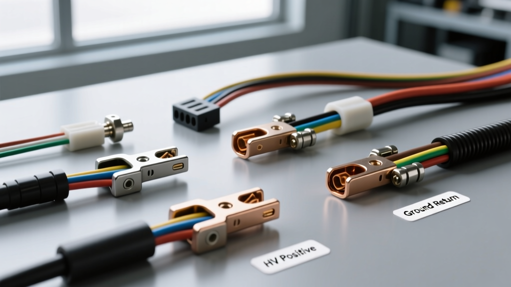
Understanding High Voltage Wire Splice Protocols in Automotive Systems
The transition toward 400V and 800V electric vehicle (EV) architectures has fundamentally changed automotive electrical repair. In modern EVs and hybrids, any circuit operating above 60V DC is classified as high voltage (HV) and is mandated by SAE J1673 to be jacketed in high-visibility orange (RAL 2003). When executing an EV swap, repairing an auxiliary HV circuit (such as an electric AC compressor or PTC heater feed), or extending harnesses for aftermarket battery management systems, selecting the correct high voltage wire splice method is a matter of safety and system integrity.
Critical Safety Warning: OEM service manuals universally prohibit splicing main traction battery cables (typically 2/0 AWG to 4 AWG) running between the battery pack and the drive inverter. These cables must be replaced as complete assemblies to maintain factory crash-safety and shielding integrity. However, for auxiliary HV circuits (16 AWG to 8 AWG), EV conversions, and off-road electric builds, a properly engineered high voltage wire splice is both necessary and safe when executed to aerospace and automotive HV standards.
Product Comparison: Top High Voltage Wire Splice Solutions
Not all connectors are rated for the dielectric stress and thermal cycling of a 400V+ automotive environment. Standard 12V PVC heat shrink barrels will suffer from partial discharge (corona effect) and catastrophic failure. Below is a comparison of the three primary HV splicing methods.
1. Adhesive-Lined Polyamide Heat Shrink Crimp Barrels
For auxiliary HV circuits (16 AWG to 6 AWG), environmentally sealed adhesive-lined crimp barrels are the industry standard. Unlike standard polyolefin, high-voltage variants utilize a dual-wall construction with an inner layer of thermoplastic polyamide or specialized dielectric mastic. When heated to 120°C, the inner wall melts and flows into the wire strands, eliminating air pockets where partial discharge could occur.
- Best For: 16 AWG to 6 AWG auxiliary lines, resolver sensor extensions, and BMS communication harnesses.
- Pros: Maintains flexibility, provides complete moisture ingress protection (IP67/IP69K), excellent dielectric strength (typically rated to 600V-1000V depending on wall thickness).
- Cons: Requires precise hex-crimp tooling; improper die selection will compromise the mechanical pull-out force and create a high-resistance hot spot.
2. Mechanical Shear-Bolt Splice Connectors
When working with larger gauge EV cables (4 AWG to 2/0 AWG) in custom builds where ultrasonic welding or massive hydraulic crimpers are unavailable, shear-bolt splice connectors are the optimal choice. These aluminum or copper-tin alloy barrels use torque-rated breakaway bolts. Once the bolt head snaps off, a specific torque (e.g., 12 Nm for an M8 bolt) has been applied, ensuring a gas-tight electrical connection regardless of the wire gauge variance.
- Best For: 4 AWG to 2/0 AWG main feed extensions in custom EV conversions and marine electric drives.
- Pros: No expensive hydraulic crimp tooling required, accommodates both copper and aluminum wire, highly reliable mechanical grip.
- Cons: Bulky profile requires heavy-duty, oversized heat shrink tubing for dielectric isolation; rigid connection point is susceptible to fatigue if not properly strain-relieved.
3. Ultrasonic Metal Welding (UMW)
Ultrasonic welding is the OEM standard for joining HV battery ribbons and cell-to-busbar connections. It uses high-frequency acoustic vibrations to create a solid-state metallurgical bond without melting the base metal. While not a traditional 'connector' you buy off the shelf, portable ultrasonic splice tools are increasingly used in high-end motorsport EV builds for 8 AWG to 2 AWG splices.
- Best For: Motorsport EV applications, battery module repair, and zero-resistance requirements.
- Pros: Lowest possible electrical resistance, no crimp barrel mass to add thermal inertia, immune to vibration-induced loosening.
- Cons: Extreme equipment cost, requires specialized training, difficult to perform in confined chassis spaces.
Technical Specification & Selection Matrix
Use the following matrix to select the appropriate high voltage wire splice method based on your specific AWG requirement and tooling availability.
| Splice Method | AWG Range | Voltage Rating | EMI Shielding Restoration | Required Tooling |
|---|---|---|---|---|
| Adhesive-Lined Crimp Barrel | 16 AWG – 6 AWG | 600V – 1000V | Braided Copper Sleeve + Mastic | Precision Hex-Crimp Pliers |
| Shear-Bolt Connector | 4 AWG – 2/0 AWG | Up to 1500V | Conductive Tape + Heavy Shrink | Calibrated Torque Wrench |
| Ultrasonic Welding | 8 AWG – 2 AWG | N/A (Bare Metal) | Post-Weld Shield Wrapping | Ultrasonic Splice Welder |
Step-by-Step: Executing an 8 AWG Auxiliary HV Splice
When repairing an 8 AWG feed line to a 400V electric power steering pump or AC compressor, you must restore both the dielectric isolation and the electromagnetic interference (EMI) shielding. Failure to restore the shield will allow high-frequency switching noise from the inverter to corrupt nearby CAN-bus networks.
- De-Energize and Verify: Disconnect the 12V service loop. Wait 15 minutes for capacitor bleed-down. Use a Category III/IV multimeter to verify 0V between the HV phases and chassis ground.
- Personal Protective Equipment: Don Class 0 high-voltage insulated gloves (rated to 1000V AC/DC per NFPA 70E standards) with leather protectors.
- Strip the Jacket and Shield: Strip back 2 inches of the orange XLPE outer jacket. Carefully fold back the braided copper EMI shield to expose the inner bare copper conductor. Do not nick the inner strands.
- Hex Crimp the Barrel: Slide the adhesive-lined HV heat shrink barrel over the wire. Using a calibrated hex-crimp tool with the exact die size for 8 AWG, crimp the bare conductor. A proper 8 AWG hex crimp should yield a pull-out force exceeding 400 lbs.
- Restore the EMI Shield: Slide a piece of tinned copper braided shielding sleeve over the exposed splice area. Overlap the sleeve with the factory folded-back shield by at least 0.5 inches. Secure the overlap with copper foil tape or a stainless-steel crimp ring.
- Seal and Shrink: Slide the outer adhesive-lined heat shrink tubing (minimum 3:1 shrink ratio, rated for 600V+) over the entire repair. Apply heat evenly from the center outward until the dielectric mastic purges slightly from the edges, indicating a complete moisture seal.
Troubleshooting HV Splice Failure Modes
Even a meticulously executed high voltage wire splice can degrade if environmental or electrical parameters are exceeded. Use the following diagnostic tree to identify HV splice faults:
- Symptom: Intermittent Inverter Fault Codes (Isolation Loss)
Cause: Moisture ingress or micro-tears in the outer heat shrink allowing chassis leakage current.
Fix: Perform an Insulation Resistance (Megger) test at 1000V DC. A healthy HV circuit should read >20 Megohms. If low, cut out the splice and replace using a longer dielectric barrier. - Symptom: Thermal Hotspot Identified via FLIR Camera (>15°C above ambient wire temp)
Cause: Under-crimped barrel or incorrect hex die used, leading to high micro-ohm resistance and I²R heating under load.
Fix: Replace the splice. Ensure the crimp tool is calibrated and the wire strands are fully seated at the bottom of the barrel before crimping. - Symptom: CAN-Bus Corruption or Resolver Signal Dropouts
Cause: EMI shield continuity broken at the splice point, radiating switching noise.
Fix: Check shield continuity with a milliohm meter. The resistance between the shield on either side of the splice must be <0.05 ohms. Re-wrap with copper braid if necessary.
Final Considerations for EV Wiring Safety
As outlined by ISO 19642 standards for road vehicle high voltage cables, the physical and electrical integrity of an EV wiring harness is paramount. Never substitute standard 12V automotive connectors for HV applications. Always verify voltage ratings, utilize proper adhesive-lined dielectric barriers, and meticulously restore the EMI shielding to ensure your high voltage wire splice survives the harsh thermal and vibrational environment of the modern electric vehicle.