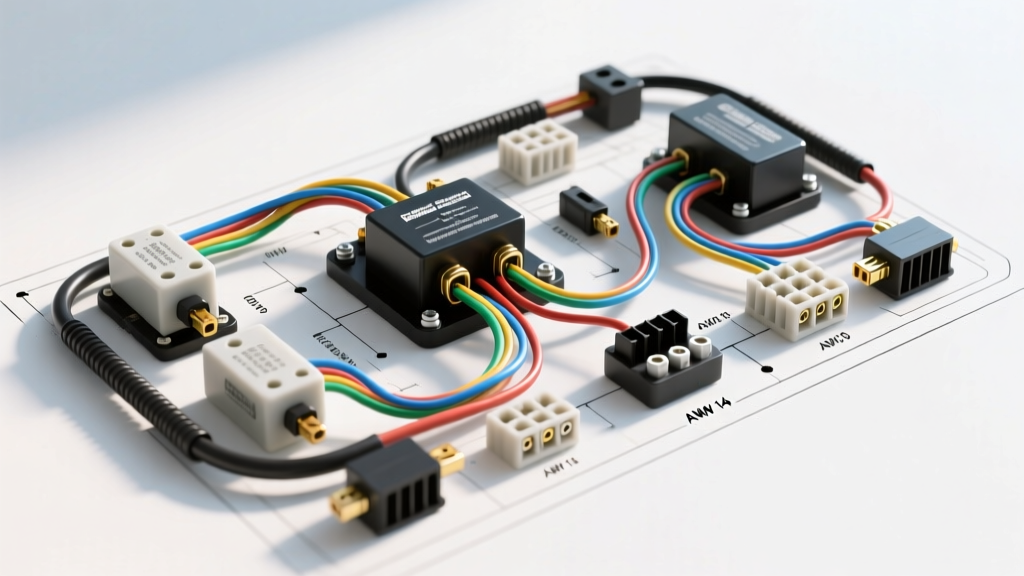
The Hidden Dangers of Improper Car Relay Repair
Automotive relays are the unsung heroes of high-amperage lighting and electrical systems. Whether you are installing a 50-inch LED light bar, upgrading to high-output H4 headlights, or wiring auxiliary fog lamps, the relay acts as the crucial bridge between a low-current trigger switch and a high-current power source. However, a flawed car relay repair or a poorly executed aftermarket installation can lead to catastrophic results. Melted wiring harnesses, destroyed Body Control Modules (BCMs), and engine bay fires are frequently traced back to fundamental misunderstandings of relay logic, wire ampacity, and terminal integrity.
As an automotive electrical specialist, I have diagnosed countless electrical gremlins caused by shortcut wiring. Below, we break down the five most critical mistakes made during car relay repair and lighting installations, complete with the exact specifications required to do the job safely and correctly.
Mistake 1: Undersizing the Control and Load Circuit Wires
The most common failure in aftermarket lighting and relay repair is relying on generic '12-volt wire' without calculating voltage drop over distance. A standard Bosch-style ISO mini relay is typically rated for 40 Amps on the load circuit (Pins 30 and 87). Many DIYers assume that 14 AWG wire is sufficient because the fuse is rated for 30A. This is a dangerous miscalculation.
The Voltage Drop Factor
According to standard automotive electrical principles, wire gauge must be selected based on both amperage and total circuit length (from the battery, through the relay, to the load, and back to ground). A 14 AWG copper wire carrying 30A over a 15-foot run will experience significant voltage drop, generating excess heat within the wire insulation. For a 40A relay powering a high-draw light bar, you must use a minimum of 10 AWG stranded copper wire for the load circuit (Pin 30 to Pin 87). If the run exceeds 12 feet, step up to 8 AWG to maintain optimal voltage at the lighting fixture.
Similarly, the control circuit (Pins 85 and 86) draws roughly 150mA to energize the coil. While 18 AWG wire is technically sufficient for short cabin runs, upgrading to 16 AWG for firewall pass-throughs prevents voltage drop that can cause the relay to chatter or fail to engage entirely when system voltage dips below 12.2V during engine cranking.
Mistake 2: Misinterpreting 5-Pin Changeover Logic (87 vs. 87a)
A standard 4-pin ISO relay features Pins 30, 85, 86, and 87. A 5-pin changeover relay adds Pin 87a. During a car relay repair involving OEM fog lights or dual-filament headlight conversions, technicians frequently confuse the Normally Open (NO) and Normally Closed (NC) terminals.
- Pin 30: Common Battery Feed (B+)
- Pin 85: Coil Ground (or Trigger, depending on polarity)
- Pin 86: Coil +12V Trigger (or Ground)
- Pin 87: Normally Open (NO) - Powers the load ONLY when the relay is energized.
- Pin 87a: Normally Closed (NC) - Powers the load when the relay is AT REST (de-energized).
The Dead Short Hazard
If you wire a high-amperage lighting load to Pin 87a by mistake, the lights will turn on when the switch is off. Worse, if you attempt to use a 5-pin relay as a polarity-reversing or changeover switch for a motorized actuator without proper isolation, energizing the coil will instantly connect the battery positive (Pin 30) to a circuit that may be grounded through the load, resulting in a dead short, blown main fuses, and potentially melted battery cables. Always verify continuity with a multimeter between Pin 30 and Pin 87a (should read near 0 ohms at rest) and Pin 30 to Pin 87 (should read infinite resistance at rest) before applying power.
Mistake 3: Ignoring Inductive Kickback and Flyback Diodes
When you perform a car relay repair on modern vehicles equipped with solid-state switches, CAN-bus multiplexers, or sensitive ECU driver circuits, omitting a flyback diode is a fatal error. A relay coil is an inductor. When the trigger circuit is broken (the switch is turned off), the collapsing magnetic field inside the coil generates a massive reverse-voltage spike—often exceeding 100 volts.
Protecting Solid-State Drivers
If your relay coil (Pins 85 and 86) is triggered by a factory headlight switch, a Body Control Module (BCM), or an aftermarket LED rocker switch with internal solid-state transistors, this inductive kickback will instantly punch through the semiconductor junction, permanently destroying the switch or module. To prevent this, you must install a 1N4007 rectifier diode across the coil terminals. The diode's cathode (marked with a silver stripe) must point toward the positive trigger source (Pin 86), and the anode to the ground (Pin 85). This creates a localized loop that safely dissipates the voltage spike back into the coil. For detailed coil suppression specifications, refer to the Littelfuse Mini ISO Datasheet.
Mistake 4: Relying on Generic Spade Terminals and Solder-Only Joints
The physical connection between the wire and the relay socket is just as critical as the wiring logic. The engine bay is a high-vibration, high-heat environment. Using generic, non-locking spade terminals pushed into an ISO mini relay socket is a recipe for arcing and melted plastic housings.
The Open-Barrel Crimp Standard
Proper car relay repair requires the use of OEM-style TE Connectivity (AMP) open-barrel crimp terminals featuring locking barbs. These barbs snap securely into the relay socket housing, preventing the terminal from backing out due to engine harmonics. Furthermore, soldering wires directly to relay pins without a proper mechanical crimp creates a rigid joint. In high-vibration zones, the solder joint will experience fatigue and crack, leading to high resistance. High resistance generates heat; a relay socket operating at 80°C+ will soften and deform, causing the internal spades to lose tension and arc. Always use a dedicated open-barrel crimping tool (such as the Delphi Packard or equivalent) and seal the joint with adhesive-lined dual-wall heat shrink tubing to prevent moisture ingress and galvanic corrosion.
Mistake 5: Fusing the Load Side Instead of the Battery Feed
Fuse placement is a critical safety parameter defined by SAE standards. A staggeringly common mistake during lighting relay installations is placing the fuse after the relay on the load wire (Pin 87), leaving the main power feed (Pin 30) completely unfused from the battery to the relay.
The SAE Standard for Overcurrent Protection
If the wire between the battery and Pin 30 chafes against the chassis or firewall, it will short directly to ground. Without a fuse on this specific segment of the wire, the battery will dump hundreds of amps into the short, turning the wire into a red-hot heating element and starting an engine bay fire. According to SAE J1284 standards and best automotive practices, the main overcurrent protection device (fuse or circuit breaker) must be installed within 18 inches of the battery positive terminal on the Pin 30 feed wire. The fuse rating must match the ampacity of the wire (e.g., a 40A MAXI fuse for 10 AWG wire, or a 50A MIDI fuse for 8 AWG wire).
Relay Failure Symptom vs. Root Cause Diagnostic Matrix
Use the following reference table to quickly diagnose issues when troubleshooting a car relay repair or aftermarket lighting failure.
| Symptom | Root Cause | Corrective Action & Specification |
|---|---|---|
| Relay clicks rapidly (chatters) under load | Voltage drop in the control circuit (Pins 85/86) causing coil dropout. | Upgrade control wire from 18 AWG to 14 AWG; check chassis ground for paint/rust. |
| Relay socket melts near Pin 30 | High resistance terminal crimp or continuous draw exceeding 35A on a 40A relay. | Replace socket with TE Connectivity locking terminals; upgrade to a 70A heavy-duty relay. |
| LED trigger switch burns out instantly | Inductive kickback from relay coil destroying solid-state switch. | Solder a 1N4007 flyback diode across Pins 85 and 86 (Cathode to +12V). |
| Light bar turns ON when switch is OFF | Load wired to Pin 87a (Normally Closed) instead of Pin 87 (Normally Open). | Move load wire from terminal 87a to terminal 87. |
| Main battery cable smokes without blowing fuse | Fuse placed on Pin 87 load side; Pin 30 battery feed is unfused and shorted. | Install MAXI fuse within 18 inches of battery positive on the Pin 30 feed wire. |
Conclusion: Precision Over Speed
A successful car relay repair or lighting upgrade requires respecting the physics of electrical current. By selecting the correct AWG wire based on total circuit length, adhering strictly to ISO mini pinout logic, suppressing inductive kickback, executing proper open-barrel crimps, and observing SAE fuse placement guidelines, you ensure a system that is not only functional but inherently safe. Never rely on twist-and-tape methods or generic hardware store spades when working under the hood; the thermal and vibrational demands of the automotive environment demand OEM-grade materials and expert-level execution.