Introduction to Automotive DC Solid State Relays (SSRs)
When upgrading high-draw auxiliary lighting, such as 50-inch LED light bars or off-road halogen fog lamps, traditional electromechanical relays (EMRs) often become the weakest link in the harness. EMRs suffer from contact bounce, mechanical wear, and susceptibility to moisture and vibration-induced failure. For modern automotive lighting applications, referencing a precise solid state relay wiring diagram is critical to achieving silent, spark-free, and highly reliable power delivery.
Unlike mechanical relays that rely on a magnetic coil and physical contacts, a Solid State Relay (SSR) utilizes semiconductor switching—typically optically isolated MOSFETs or Thyristors. In 12V and 24V DC automotive environments, selecting the correct SSR architecture and following strict wire gauge specifications ensures your lighting system operates safely without inducing parasitic draws or catastrophic thermal failures.
MOSFET vs. Thyristor Architecture: A Critical Distinction
Before executing any solid state relay wiring diagram, you must verify the internal semiconductor architecture. Not all DC SSRs are created equal, and using the wrong type in a 12V automotive system will result in melted housings and failed harnesses.
- Thyristor/SCR-based DC SSRs: These exhibit a forward voltage drop of approximately 1.1V to 1.4V. At a 40A load (typical for a 500W off-road light bar), a Thyristor SSR will dissipate roughly 48 Watts of heat (P = V × I). This requires massive, heavily finned aluminum heat sinks and active cooling, making them entirely unsuitable for sealed automotive lighting harnesses.
- MOSFET-based DC SSRs: Modern automotive-grade DC SSRs utilize N-Channel or P-Channel MOSFETs with an extremely low On-Resistance (RDS(on)). A high-quality 40A MOSFET SSR might have an RDS(on) of just 1.5 milliohms (0.0015Ω). At 40A, the heat dissipation is a mere 2.4 Watts (P = I²R). This negligible thermal output allows the SSR to be potted in a compact, sealed IP67 housing without an external heat sink.
Always source MOSFET-based DC SSRs for 12V/14.4V automotive lighting circuits. According to application guidelines from Sensata Technologies, verifying the internal voltage drop and thermal resistance (Rth(j-a)) is mandatory for DC load switching in confined vehicular spaces.
Standard High-Side Solid State Relay Wiring Diagram
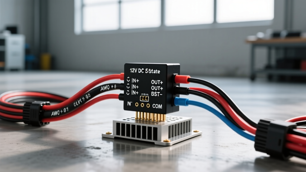
Automotive best practices dictate high-side switching (interrupting the positive voltage path) to prevent short-to-ground fires if the wiring chafes against the chassis. Below is the standard 4-pin high-side MOSFET SSR pinout and wiring matrix for auxiliary lighting.
| Pin Number | Function | Connection Point | Wire Gauge (AWG) | Connector Type |
|---|---|---|---|---|
| Pin 1 (Control +) | Logic Trigger Input | Cabin Switch / BCM / Microcontroller (3V - 32V DC) | 18 AWG | Deutsch DT 2-Pin |
| Pin 2 (Control -) | Logic Ground | Clean Chassis Ground or ECU Ground Plane | 18 AWG | Ring Terminal (M6) |
| Pin 3 (Load In) | Battery Power Source | 12V Battery Positive (via 50A MEGA/ANL Fuse) | 8 AWG TXL | Ring Terminal / Weatherpack |
| Pin 4 (Load Out) | Switched Power Output | Light Bar Positive Input Wire | 8 AWG TXL | Deutsch DT 2-Pin (High Amp) |
Wiring Execution Notes
When routing the control circuit (Pins 1 and 2), ensure the trigger wire is isolated from high-current alternator output cables to prevent electromagnetic interference (EMI) from falsely triggering the SSR's optocoupler. The Bosch Automotive Electrics Handbook recommends maintaining a minimum 4-inch separation between 12V logic triggers and high-amperage charging circuits.
AWG Wire Sizing & Connector Standards (SAE J1128)
Proper wire sizing is non-negotiable in high-current lighting systems. Voltage drop not only dims your LED or halogen output but also forces the SSR to operate at higher current thresholds to compensate for system inefficiencies. All wiring should comply with SAE J1128 Low Tension Primary Cable standards, specifically utilizing Cross-Linked Polyethylene (TXL or GXL) insulation, which withstands under-hood temperatures up to 125°C.
| Wire Gauge (AWG) | Max Continuous Ampacity | Voltage Drop at 20A Load | Voltage Drop at 40A Load | Recommended Application |
|---|---|---|---|---|
| 14 AWG TXL | 15A | 0.51V | 1.02V (Exceeds safe limits) | LED Rock Lights, Interior Pods |
| 12 AWG TXL | 20A | 0.32V | 0.64V | Small Fog Lamps (Up to 240W) |
| 10 AWG TXL | 30A | 0.20V | 0.40V | Standard 30-inch LED Light Bars |
| 8 AWG TXL | 50A | 0.13V | 0.26V | 50-inch Light Bars, Winch Solenoids |
PWM Dimming & Microcontroller Integration
One of the most significant advantages of utilizing a solid state relay wiring diagram over a mechanical setup is native Pulse Width Modulation (PWM) compatibility. Mechanical relays will rapidly destroy their internal contacts if subjected to PWM switching frequencies. Conversely, MOSFET-based SSRs can switch thousands of times per second without degradation.
Integrating CAN-Bus and Arduino Controllers
If you are integrating your auxiliary lighting into a custom CAN-bus keypad or an Arduino-based logic controller, wire the microcontroller's PWM output pin directly to Pin 1 (Control +) of the SSR.
- Switching Frequency: Keep the PWM frequency between 200Hz and 1kHz. Frequencies below 100Hz may cause visible flickering in LED light bars with inadequate internal capacitors, while frequencies above 5kHz can cause excessive switching losses (heat) within the SSR's internal logic gate drivers.
- Logic Level Shifting: Most automotive DC SSRs accept a control voltage range of 3VDC to 32VDC. This means a 5V Arduino Uno or a 3.3V Raspberry Pi can trigger the SSR directly without the need for an intermediate logic-level MOSFET or flyback diode, as the SSR's internal optocoupler handles the isolation.
Thermal Management & Heat Sink Calculations
Even with highly efficient MOSFET architectures, thermal management must be calculated based on the specific ambient under-hood temperatures. Automotive engine bays frequently see ambient temperatures of 85°C to 105°C near the firewall or radiator support.
To calculate the required thermal dissipation, use the following formula:
Tj = Ta + (Pdiss × Rth(j-a))
Where:
- Tj = Junction Temperature (Max typically 150°C for automotive silicon)
- Ta = Ambient Temperature (e.g., 90°C under-hood)
- Pdiss = Power Dissipated (I² × RDS(on))
- Rth(j-a) = Thermal Resistance from Junction to Ambient (provided in the SSR datasheet, typically 60°C/W for un-heatsinked PCB mounts, or 2°C/W for chassis-mounted units).
For a 40A continuous load on an SSR with an RDS(on) of 0.002Ω, Pdiss is 3.2W. If the SSR is mounted to a metal bracket acting as a heat sink (Rth(j-a) = 4°C/W), the temperature rise is only 12.8°C above ambient. This confirms that chassis-mounting the SSR to a steel or aluminum body panel using thermal paste and M4 stainless steel hardware is sufficient for high-draw lighting applications.
Troubleshooting & Failure Mode Analysis
Solid state relays fail differently than electromechanical relays. While an EMR typically fails 'open' (lights won't turn on due to pitted contacts), an SSR subjected to over-current or voltage spikes typically fails 'shorted' (lights remain on permanently). This is a critical safety consideration for your wiring diagram.
Diagnostic Decision Tree
- Symptom: Auxiliary lights remain ON when the cabin switch is OFF.
Cause: The internal MOSFET has suffered a dielectric breakdown and shorted between Drain and Source, likely due to an inductive voltage spike from a failing LED driver.
Fix: Replace the SSR. Install an external bidirectional TVS (Transient Voltage Suppression) diode across Pins 3 and 4 to clamp future inductive spikes. - Symptom: Lights do not turn ON, but Control LED on SSR is illuminated.
Cause: The optocoupler is functioning (logic side is healthy), but the output MOSFET gate driver has failed, or the main inline MEGA fuse has blown.
Fix: Test voltage at Pin 3 (Load In). If 12V is present, test Pin 4 (Load Out) while triggered. If 0V, the SSR output stage is dead. Replace SSR. - Symptom: SSR casing is melting or too hot to touch.
Cause: You have mistakenly installed a Thyristor-based DC SSR instead of a MOSFET-based SSR, or the wire gauge on Pins 3 and 4 is too thin, causing voltage drop and heat generation at the crimp terminals.
Fix: Verify SSR part number architecture. Upgrade to 8 AWG TXL wire and use sealed, adhesive-lined heat shrink crimps for all ring terminals.
By strictly adhering to these MOSFET specifications, AWG routing guidelines, and thermal calculations, your solid state relay wiring diagram will yield an automotive lighting system that is vastly superior in longevity, safety, and performance compared to traditional mechanical harnesses.