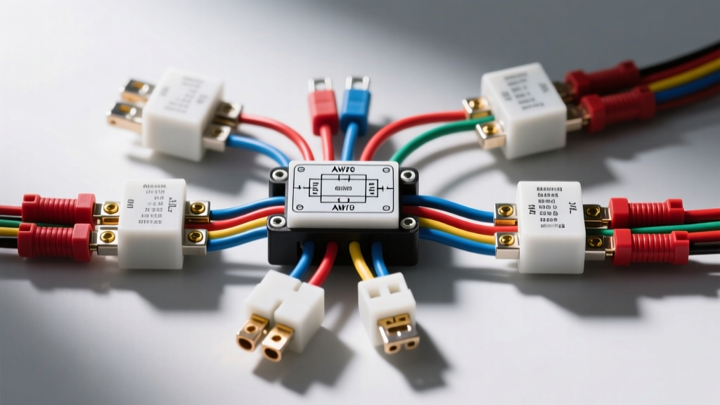
The Engineering Case for a Car Headlight Relay Upgrade
Most classic and economy vehicles route headlight power directly from the battery, through the ignition switch, into the dashboard headlight switch, and finally out to the front lamps. This factory topology relies on long runs of thin 16 AWG or 18 AWG copper wire. According to Ohm's law, pushing 10 to 15 amps through these undersized, decades-old conductors results in severe voltage drop. Halogen bulbs are notoriously sensitive to voltage deficits; a mere 5% drop in voltage yields a disproportionate 15% loss in luminous flux. Installing a dedicated car headlight relay harness bypasses the factory switching architecture, delivering full battery voltage directly to the bulbs via heavy-gauge wiring.
In this complete wiring diagram walkthrough, we will dissect the anatomy of a professional-grade headlight relay upgrade. We will cover standard ISO mini relay pinouts, precise AWG wire selections, high-temperature insulation requirements, and the critical diode logic required for dual-filament H4 headlight setups.
Standard ISO Mini Relay Pinout Reference
The automotive industry predominantly utilizes the Bosch-standard ISO 7588 mini relay for high-current lighting circuits. Understanding the terminal numbering is mandatory before cutting a single wire. The internal electromagnet and the high-current contact switch are completely isolated from one another.
| Terminal / Pin | Function | Wire Gauge Spec | Circuit Role |
|---|---|---|---|
| 30 | Common (Power Input) | 10 AWG GXL | Direct battery power feed (fused) |
| 87 | Normally Open (Output) | 10 AWG GXL | Load feed to headlight positive terminal |
| 85 | Coil Ground | 16 AWG TXL | Chassis ground for the electromagnet |
| 86 | Coil Trigger (Input) | 16 AWG TXL | Switched 12V+ from factory headlight wire |
When 12 volts is applied across pins 85 and 86, the internal coil energizes, creating a magnetic field that pulls the contactor down. This bridges pins 30 and 87, allowing high-amperage current to flow to your headlights. For a comprehensive overview of relay switching mechanics and contact materials, refer to the Bosch Mobility Solutions relay documentation.
Phase 1: Power and Ground Routing (The Load Circuit)
Selecting the Correct Wire Insulation
Never use standard PVC-insulated wire (like THHN or primary wire) under the hood. Engine bay temperatures easily exceed the 90°C melting point of PVC, leading to short circuits against the chassis. You must use GXL (General Cross-Linked) or TXL (Thin-wall Cross-Linked) automotive wire. These feature polyethylene insulation rated for 125°C to 150°C and possess superior resistance to automotive fluids, oil, and abrasion.
Routing Pin 30 (Main Power)
Begin at the battery positive terminal. Crimp a heavy-duty, heat-shrink-sealed ring terminal onto a length of 10 AWG GXL wire. Route this wire to an inline SAE J1284 compliant ATO/ATC fuse holder. For standard 55W H4 or H7 bulbs (drawing roughly 4.5 amps each), a 15A or 20A blade fuse is optimal. The fuse must be located within 18 inches of the battery terminal to protect the entire downstream harness in the event of a dead short. From the fuse, the 10 AWG wire routes to Pin 30 of the relay.
Routing Pin 87 (Load Output)
Pin 87 carries the switched power to the headlight bulb. Use 10 AWG GXL wire to bridge Pin 87 to the positive terminal of the headlight connector. If you are upgrading to 100W off-road rally bulbs, you must step up to 8 AWG wire to prevent voltage drop across the harness run. Terminate the end with a Delphi Weather-Pack 150-series or Deutsch DT connector to ensure a waterproof seal at the headlight housing.
Phase 2: Trigger Circuit Integration (The Control Circuit)
The control circuit requires significantly less current—typically under 200 milliamps—because it only needs to energize the relay's internal copper coil. Therefore, 16 AWG or even 18 AWG TXL wire is perfectly adequate for Pins 85 and 86.
Sourcing the Trigger Signal
Locate the factory headlight connector on the side of the vehicle where the relay will be mounted. Using a digital multimeter, back-probe the factory wires to identify the positive feed that becomes 'hot' when the headlight switch is turned on. Splice a 16 AWG trigger wire into this factory positive feed using a solder-and-heat-shrink method or a sealed gel-crimp connector. Route this wire to Pin 86 on the relay.
Establishing the Coil Ground
Connect a 16 AWG wire to Pin 85. Route this to a clean, unpainted metal location on the chassis or directly to the negative battery terminal. If grounding to the chassis, sand away the paint and e-coat down to bare steel, use a star washer to bite into the metal, and coat the terminal in dielectric grease to prevent galvanic corrosion. A poor ground here will result in a weak magnetic field, causing the relay to chatter or fail to pull the high-current contactor fully closed.
Phase 3: Dual-Filament H4 Headlight Logic and Backfeed Prevention
If your vehicle utilizes H4 (9003) dual-filament bulbs for both high and low beams, a single relay is insufficient. You must deploy a dual-relay harness—one relay dedicated to the low-beam filament, and a second dedicated to the high-beam filament. However, this introduces a notorious electrical anomaly known as 'backfeed.'
The Backfeed Phenomenon
In an H4 bulb, the low-beam and high-beam filaments share a common ground wire inside the glass envelope. When you trigger the high-beam relay, 12V+ flows into the high-beam filament. Because the low-beam relay is currently open (off), the electricity seeks a path to ground. It travels backward through the low-beam filament, out through the low-beam trigger wire, and into the dashboard circuitry. This can cause your dashboard high-beam indicator to behave erratically, or worse, feed voltage back into the headlight switch, melting factory wiring.
The Diode Solution
To prevent backfeed, you must install a blocking diode on the low-beam trigger wire. As detailed in the legendary lighting tutorials by Daniel Stern, a standard 1N5408 (3-amp) or 1N4001 (1-amp) silicon rectifier diode is required. Solder the diode in-line on the 16 AWG trigger wire feeding the low-beam relay's Pin 86. Ensure the diode's silver band (the cathode) faces toward the relay. This acts as a one-way electrical valve, allowing the factory switch to trigger the relay, but blocking any reverse voltage from the high-beam circuit.
Troubleshooting Voltage Drop and Relay Chatter
Even with a flawless diagram walkthrough, real-world variables can compromise your car headlight relay installation. Use this diagnostic tree to isolate faults:
- Symptom: Headlights are bright, but relay clicks rapidly (chatter).
Cause: Voltage drop on the trigger circuit. The factory headlight switch cannot supply enough amperage to hold the relay coil closed once the heavy load engages.
Fix: Install a secondary 'master' relay to buffer the trigger signal, or clean and apply contact enhancer to the factory headlight switch internals. - Symptom: Relays click, but headlights remain dim.
Cause: High resistance on the load side (Pin 87 to bulb) or a corroded chassis ground.
Fix: Perform a loaded voltage drop test. Set your multimeter to DC Volts. Place the red probe on the battery positive post and the black probe on the headlight positive terminal while the lights are ON. A reading above 0.2V indicates undersized wire or a bad crimp. Repeat on the ground side (battery negative to bulb ground). - Symptom: Relay gets excessively hot to the touch.
Cause: Using a cheap, off-brand relay with high internal contact resistance, or exceeding the 30A continuous rating of an ISO mini relay with high-wattage bulbs.
Fix: Replace with a genuine Bosch or Hella ISO mini relay. If running 100W+ bulbs, upgrade to an ISO Maxi relay rated for 50A+ continuous duty.
Final Torque and Sealing Specifications
Secure all ring terminals to the battery and chassis using a calibrated torque wrench or a properly sized socket. Battery terminal nuts typically require 5 to 7 Nm (44-62 lb-in) of torque. Over-tightening will strip the soft lead of the battery post or snap the terminal stud. Finally, inject a small amount of dielectric grease into all Weather-Pack and Deutsch connector cavities before mating them. This displaces moisture and prevents the formation of copper oxide, ensuring your car headlight relay harness delivers maximum luminous efficiency for years to come.