Translating Logical Schematics to Physical Automotive Harnesses
In the realm of automotive electrical engineering and aftermarket lighting upgrades, terminology often overlaps depending on the manufacturer, the era of the service manual, or the region of origin. When reading through factory service manuals or aftermarket lighting instructions, you will frequently encounter notes stating that connection diagrams are also called wiring diagrams. While electrical purists and SAE standards bodies differentiate between a purely logical schematic (which shows circuit flow regardless of physical location) and a physical wiring diagram (which maps exact harness routing, splice locations, and chassis grounds), the practical reality for an automotive technician is that both must be understood simultaneously to execute a flawless installation.
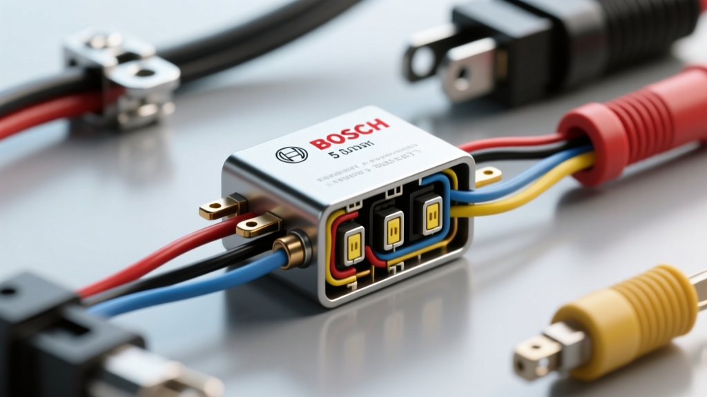
This complete wiring diagram walkthrough focuses on one of the most common, yet frequently botched, lighting upgrades: bypassing factory headlight switches to power high-draw H4/9003 LED or HID conversion kits using a Bosch-style ISO Mini 5-pin relay. By understanding how the logical connection diagram translates into physical wire gauges, terminal crimps, and routing paths, you can eliminate voltage drop, prevent melted factory connectors, and ensure optimal lumen output from your aftermarket lighting.
Decoding the Standard 5-Pin Automotive Relay Schematic
The backbone of heavy-duty automotive lighting is the ISO Mini 5-pin relay. Standardized under DIN 72552 terminal designations, this relay isolates the high-amperage load circuit from the low-amperage trigger circuit. When interpreting the connection diagram for an H4 dual-beam headlight relay harness, you must identify the coil circuit (electromagnet) and the switch circuit (high-current contacts).
According to TE Connectivity Automotive Relay Application Guidelines, a standard 12V ISO mini relay coil typically draws between 150mA and 200mA, while the switched contacts are rated for 30A continuous and up to 40A peak. To handle these loads safely, your physical wiring must adhere to strict AWG (American Wire Gauge) requirements.
DIN 72552 Terminal Specifications & Wire Mapping
| DIN Pin | Function | Standard Wire Color | Required AWG | Circuit Type |
|---|---|---|---|---|
| 30 | Common Input (Power) | Red | 10 AWG | Switched Load (Battery +) |
| 85 | Coil Ground | Black | 14 AWG | Control Circuit (Chassis -) |
| 86 | Coil Trigger (Input) | White | 14 AWG | Control Circuit (Factory H4 +) |
| 87 | Normally Open (NO) Output | Blue | 10 AWG | Switched Load (LED Ballast +) |
| 87a | Normally Closed (NC) Output | Yellow | 14 AWG (Unused) | Switched Load (Isolated) |
Step-by-Step Walkthrough: Building the H4 Relay Harness
When a manual states that connection diagrams are also called wiring diagrams, it expects the technician to map the schematic symbols to physical components. Here is how to physically build and route the H4 relay harness using automotive-grade materials.
Step 1: The Power Feed (Pin 30)
The logical schematic simply shows a line from the battery to Pin 30. The physical wiring diagram dictates that you must use SAE J1128 GXL or TXL wire, which features cross-linked polyethylene insulation rated for 125°C. Cut a length of 10 AWG red TXL wire. Crimp a 10 AWG closed-ring terminal on one end and an inline ATO fuse holder on the other. Route this wire directly to the positive battery terminal, ensuring the 30A blade fuse is positioned within 6 inches of the battery post to protect the entire harness in the event of a short to ground.
Step 2: The Trigger Circuit (Pins 85 & 86)
Pin 86 receives the low-current trigger signal from the factory H4 headlight plug. Because modern vehicles use multiplexed CAN-bus systems or PWM (Pulse Width Modulation) for daytime running lights, connecting directly to the factory headlight wire can cause relay chatter. To prevent this, use a T-tap or cut the factory low-beam positive wire, routing it to Pin 86 using 14 AWG white wire. Pin 85 must be grounded. Do not rely on random sheet metal screws; locate a dedicated chassis ground stud (often M6 or M8), remove any paint or powder coating with a wire wheel, and secure the 14 AWG black wire using a star washer to ensure a resistance reading of less than 0.05 ohms.
Step 3: The Load Output (Pin 87)
Pin 87 delivers the full battery voltage to the aftermarket LED or HID ballast. Run 10 AWG blue wire from Pin 87 to the relay socket, and transition to a Delphi Weather-Pack 2-pin connector at the headlight housing. Using Weather-Pack connectors with silicone secondary locks ensures the connection remains watertight (IP67 rated) and vibration-resistant, preventing the infamous 'green crust' corrosion that plagues standard spade terminals.
Real-World Failure Modes & Troubleshooting
Even when connection diagrams are also called wiring diagrams and followed perfectly, real-world variables can introduce faults. Here is a diagnostic decision tree for common relay lighting failures:
Symptom: Rapid Relay Chatter or Flickering Lights
- Cause A: Poor Coil Ground (Pin 85). If the ground circuit has high resistance, the electromagnetic coil cannot generate enough flux to fully pull the contacts closed, causing them to bounce.
- Fix: Perform a voltage drop test across Pin 85 and the negative battery terminal with the headlights on. A reading above 0.1V indicates a bad ground. Relocate the ground ring terminal to a bare metal strut tower bolt.
- Cause B: CAN-bus Backfeed. The vehicle's BCM (Body Control Module) is sending a pulsed diagnostic check signal through the headlight circuit.
- Fix: Install a 1N4007 flyback diode across Pins 85 and 86 (stripe facing Pin 86) to absorb inductive kickback, or install a CAN-bus error canceller capacitor module inline with the trigger wire.
Symptom: Dim Aftermarket Lights / Low Lumen Output
- Cause: Severe voltage drop on the load circuit. Many cheap, pre-made relay harnesses use copper-clad aluminum (CCA) wire stamped as 12 AWG, which actually performs closer to 14 AWG.
- Fix: Measure voltage directly at the battery with the lights on, then measure voltage at the input of the LED driver/ballast. If the drop exceeds 0.5V, replace the harness with pure copper 10 AWG SAE J1128 TXL wire. Ensure all open-barrel crimps are performed with a proper ratcheting crimp tool (e.g., Delphi 12094429 equivalent) to achieve a gas-tight, cold-weld connection.
Conclusion: Bridging the Gap Between Theory and Metal
Understanding that connection diagrams are also called wiring diagrams is more than a lesson in semantics; it is a fundamental requirement for automotive electrical troubleshooting. A schematic tells you how the circuit functions logically, but the physical wiring diagram dictates how it survives the harsh, high-vibration, high-temperature environment of an engine bay. By adhering to DIN 72552 pinouts, utilizing SAE-rated TXL wiring, and executing gas-tight crimps on Weather-Pack terminals, your lighting relay upgrades will deliver maximum brightness and long-term reliability.