Understanding the Standard DIN 72552 Relay Pinout
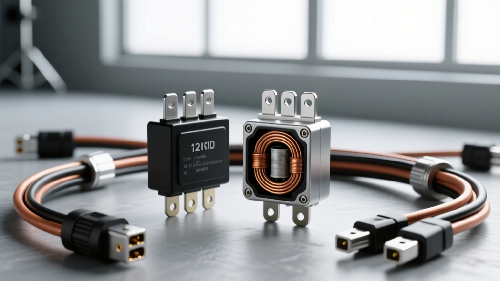
Before you learn how to test a car relay, you must understand the anatomy of the component. The vast majority of automotive lighting relays—including those used for headlight upgrades, fog light kits, and LED light bars—adhere to the DIN 72552 international standard for terminal numbering. A standard 12V electromechanical relay contains two isolated circuits: the low-current control circuit (the electromagnetic coil) and the high-current load circuit (the mechanical switch). When the coil is energized, it creates a magnetic field that pulls a metal contactor closed, allowing high amperage to flow to your lighting accessories.
According to Hella's automotive electrical guidelines, identifying the correct pins is the most critical step in relay troubleshooting. Misidentifying pins can result in a dead short, blown fuses, or melted wiring harnesses.
| Pin Number | Function | Typical Wire Color | Recommended AWG (Load vs Trigger) |
|---|---|---|---|
| 30 | Common (Load Power In) | Red / Heavy Gauge | 10 AWG (30A) or 12 AWG (20A) |
| 85 | Coil Ground | Black | 16 AWG or 18 AWG |
| 86 | Coil Power (Trigger/Signal) | Yellow / Blue | 16 AWG or 18 AWG |
| 87 | Normally Open (NO) Load Out | Blue / White | 10 AWG (30A) or 12 AWG (20A) |
| 87a | Normally Closed (NC) Load Out (5-pin only) | Green / Orange | 12 AWG or 14 AWG |
Tools Required for Relay Testing
To properly diagnose a faulty relay, you cannot rely solely on the 'click' test. Internal contact pitting or coil degradation requires precision measurement. You will need:
- Digital Multimeter (DMM): Capable of measuring Resistance (Ohms/Ω) and Continuity (audible beep).
- 12V Power Source: A spare 12V battery, a bench power supply, or a portable lithium jump-starter pack.
- Fused Jumper Wires: 14 AWG or 16 AWG wires with inline 5A fuses for the live bench test to prevent accidental short circuits.
- Alligator Clips: For hands-free probing during continuity tests.
Phase 1: Testing the Control Circuit (The Coil)
The control circuit consists of a spool of copper wire wrapped around an iron core. Your goal here is to verify that the coil is intact—neither broken (open) nor melted together (shorted).
- Set your DMM to Ohms (Ω): Select the lowest resistance range (usually 200Ω).
- Probe Pins 85 and 86: Place one multimeter probe on Pin 85 and the other on Pin 86. Polarity does not matter for standard coils.
- Read the Measurement: A healthy 12V automotive relay coil will typically display a resistance between 50Ω and 120Ω.
- Interpret the Results:
- Reading is 50Ω - 120Ω: The coil is healthy.
- Reading is 'OL' (Open Line) or Infinity: The internal copper wire is snapped. The relay is dead and must be replaced.
- Reading is near 0.0Ω: The coil has shorted out internally. It will draw excessive current and likely blow your lighting circuit fuse.
Expert Note: Some modern OEM relays (particularly those used in European vehicles for daytime running lights) contain an internal suppression diode to prevent voltage spikes. If you are testing a diode-protected relay, swap your multimeter probes between 85 and 86. You should see a standard resistance reading in one direction, and an 'OL' reading when reversed.
Phase 2: Testing the Load Circuit (The Switch)
The load circuit handles the heavy amperage required by halogen bulbs, HID ballasts, or high-output LED light bars. You must test the mechanical contacts for proper isolation and connection.
- Set your DMM to Continuity (Beep Mode):
- Test Pins 30 and 87 (Normally Open): With the relay completely unpowered (removed from the vehicle harness), touch the probes to Pin 30 and Pin 87. Expected Result: No continuity (OL). The circuit should be open.
- Test Pins 30 and 87a (5-Pin Relays Only): Touch the probes to Pin 30 and Pin 87a. Expected Result: Continuity (beep). In a 5-pin relay, power flows to 87a when the relay is at rest.
Phase 3: The Live Bench Test (Energizing the Coil)
A relay might pass static multimeter tests but fail under load due to carbon buildup on the contactor plate. The Littelfuse Automotive Relay Application Guide emphasizes that dynamic load testing is the only way to verify voltage drop across the switch.
- Apply 12V to the Coil: Using your fused jumper wires, connect 12V positive to Pin 86 and ground to Pin 85. You should hear a distinct, sharp 'click' as the electromagnetic armature pulls the contactor down.
- Re-test Continuity (30 to 87): While keeping the 12V power applied to the coil, check continuity between Pin 30 and Pin 87. Expected Result: The multimeter should beep, indicating the circuit is closed.
- Check for Contact Resistance: Switch your DMM back to Ohms (lowest setting) and measure across 30 and 87 while energized. A pristine relay will read 0.01Ω to 0.05Ω. If you read 0.5Ω or higher, the internal copper contacts are pitted or oxidized. This resistance will generate severe heat and cause a massive voltage drop, resulting in dim headlights or flickering LED bars.
Real-World Lighting Applications and Wire Sizing
Understanding how to test a car relay is only half the battle; knowing how to wire it correctly for specific automotive lighting applications prevents premature relay failure.
Upgrading H4 Halogen Headlights
Factory headlight wiring in older vehicles (e.g., 1990s Honda Civics or Jeep Cherokees) often routes full headlight current through the dashboard switch and thin 18 AWG wires. This causes severe voltage drop and melted switches. When installing a heavy-duty headlight relay harness:
- Pin 30 (Battery Feed): Use 10 AWG stranded copper wire routed directly to the battery positive terminal, protected by a 30A MAXI fuse.
- Pin 86 (Trigger): Use 16 AWG wire tapped into the factory H4 headlight plug. The factory plug now only carries the low-current signal to energize the relay coil.
- Pins 87 (Load Out): Use 12 AWG wire to feed the new H4 ceramic pigtail connectors.
Off-Road LED Light Bars
A 120W LED light bar draws roughly 10 Amps. While a standard 30A/40A relay is sufficient, the high inrush current of LED drivers can cause arcing across Pin 30 and Pin 87 upon startup. Always use a relay with a built-in arc suppressor or wire a 1N5408 flyback diode in parallel with the coil (across 85 and 86) to protect your dashboard toggle switch from inductive voltage spikes.
Troubleshooting Decision Tree: Common Relay Failure Modes
Use this diagnostic tree when your lighting circuit fails to operate after testing the relay.
- Symptom: Relay clicks rapidly or buzzes, but lights do not turn on.
- Cause: Insufficient trigger voltage reaching Pin 86, often due to a poor ground on Pin 85 or a voltage drop in the factory trigger wire.
- Fix: Measure voltage between 86 and 85 while the switch is ON. If it reads below 10.5V, clean the ground connection or run a dedicated trigger wire.
- Symptom: Relay does not click, lights do not work, but multimeter shows 12V at Pin 86.
- Cause: Open coil (internal wire break) or Pin 85 ground is completely severed.
- Fix: Perform Phase 1 coil resistance test. Replace relay if OL.
- Symptom: Relay clicks, but LED light bar flickers or halogen bulbs are dim.
- Cause: High contact resistance inside the relay (pitted contacts) or undersized wire on Pin 30/87.
- Fix: Perform Phase 3 dynamic resistance test. If resistance is >0.1Ω, replace the relay with a high-quality Bosch or TYCO unit and verify 10 AWG wire is used for the load circuit.
- Symptom: Relay gets extremely hot to the touch and melts the plastic socket.
- Cause: Overloading the relay (e.g., running a 250W light bar on a 20A relay) or using cheap, thin-stamped brass terminal pins instead of solid copper alloy pins.
- Fix: Calculate total wattage / 12V = Amperage. Ensure your relay rating exceeds the load by at least 25%. Upgrade to a heavy-duty 40A relay with ceramic socket inserts.
Mastering how to test a car relay with a digital multimeter transforms you from a parts-swapper into a true automotive electrical diagnostician. By verifying both the electromagnetic coil and the mechanical load contacts, you ensure your auxiliary lighting, headlight upgrades, and fog light installations operate reliably for years to come.