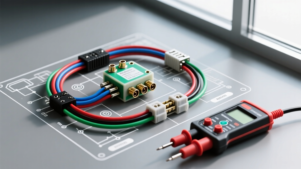
Introduction: Tracing the Circuit with a Car Relay Tester
When upgrading lighting systems or diagnosing a dead headlight circuit, guessing which component failed is a waste of time and money. The most efficient method is a systematic wiring diagram walkthrough using a dedicated car relay tester or a high-quality digital multimeter (DMM). Relays are the electromechanical bridges between your vehicle's low-current switch circuits and high-current lighting loads. By mapping your tester probes directly to the nodes on a standard Bosch-style ISO mini relay wiring diagram, you can isolate failures in seconds.
In this comprehensive walkthrough, we will decode the DIN 72552 terminal standard, perform step-by-step coil and switch circuit tests, and integrate these findings into a real-world headlight relay upgrade diagram.
Decoding the ISO Relay Wiring Diagram (DIN 72552)
Before touching your car relay tester to the terminals, you must understand the schematic symbols and terminal designations used in automotive wiring diagrams. The German Institute for Standardization (DIN) established the 72552 standard, which assigns specific numbers to relay pins. According to Bosch Automotive Aftermarket technical documentation, these numbers are universal across 90% of passenger vehicles and heavy trucks.
| Terminal | Diagram Label | Function | Typical Wire Color | AWG Rating |
|---|---|---|---|---|
| 30 | Common / Line | Main power input from battery or fuse panel | Red or Black | 10 - 12 AWG |
| 85 | Coil Ground | Ground path for the electromagnet coil | Black or Brown | 14 - 16 AWG |
| 86 | Coil Power | Switched 12V+ trigger from cabin switch or ECU | Yellow, Blue, or White | 14 - 16 AWG |
| 87 | Normally Open (NO) | Output to the load (e.g., headlights, light bar) | Blue or Green | 12 - 14 AWG |
| 87a | Normally Closed (NC) | Output when relay is at rest (5-pin SPDT only) | Orange or Purple | 12 - 14 AWG |
Step-by-Step Car Relay Tester Walkthrough: 4-Pin SPST Relay
A 4-pin Single Pole Single Throw (SPST) relay is the standard workhorse for fog lights, off-road light bars, and horn circuits. Here is how to walk through the diagram using your tester.
Phase 1: Testing the Electromagnet Coil (Pins 85 & 86)
- Locate Diagram Nodes 85 and 86: On your schematic, these represent the low-current control circuit.
- Set Tester to Ohms (Ω): Configure your car relay tester or DMM to measure resistance.
- Probe the Terminals: Place one probe on Pin 85 and the other on Pin 86. Polarity does not matter for a standard resistance check.
- Analyze the Reading: A healthy 12V automotive relay coil will typically read between 65 and 90 ohms. If the tester reads 'OL' (Open Line), the internal copper winding is snapped. If it reads near 0.0 ohms, the coil is shorted internally.
Phase 2: Testing the High-Current Switch (Pins 30 & 87)
- Locate Diagram Nodes 30 and 87: These represent the high-current load circuit.
- Set Tester to Continuity / Diode Mode: You want the tester to beep when resistance is near zero.
- Probe the Terminals (De-energized): Place probes on 30 and 87. The tester should read 'OL' or show infinite resistance. If it beeps now, the internal contacts are welded shut—a common failure mode in stuck fog light circuits.
- Energize the Coil: Use a jumper wire from a 12V source to Pin 86, and ground Pin 85. You should hear a distinct mechanical 'click'.
- Probe Again (Energized): With the coil energized, the tester should now beep and display a voltage drop of less than 0.2 ohms across pins 30 and 87. Higher resistance indicates pitted or carbon-fouled internal contacts, which will cause severe voltage drop at your headlights.
Advanced Walkthrough: 5-Pin SPDT Relay Testing
Five-pin Single Pole Double Throw (SPDT) relays introduce Terminal 87a. These are frequently used in daytime running light (DRL) modules or headlight cutoff solenoids where a circuit must be broken when another is engaged.
When walking through a 5-pin diagram with your car relay tester, you must test both states of the switch:
- At Rest (De-energized): Continuity should exist only between Pin 30 and Pin 87a. Pins 30 and 87 must read 'OL'.
- Engaged (Energized): The internal armature shifts. Continuity must now exist only between Pin 30 and Pin 87. Pins 30 and 87a must read 'OL'.
Expert Insight: If your tester shows continuity between 87 and 87a at any point, the internal insulator has melted, and the relay is a fire hazard. Discard it immediately.
Integrating the Tester into a Vehicle Lighting Diagram
Let's apply this walkthrough to a real-world scenario: upgrading the headlight circuit on a 2005 Jeep Wrangler (TJ) using a standard Bosch ISO mini relay harness to bypass the factory multifunction switch.
Diagram Node Verification Sequence
Follow the wiring diagram from the battery to the H4 bulb, using your tester at each junction to verify the installation before applying full power.
- Battery to Pin 30: The diagram calls for a 10 AWG Red wire routed through a 30A Maxi fuse. Use your tester in voltage mode to verify 12.6V at the relay socket's Pin 30 cavity before inserting the relay.
- OEM Trigger to Pin 86: The diagram taps the factory headlight positive wire (usually 16 AWG Yellow/Red tracer) to feed Pin 86. Backprobe the socket with your tester; have an assistant turn on the headlights. You should read 11.5V to 12.2V.
- Chassis Ground to Pin 85: The diagram specifies a 14 AWG Black wire terminated with a ring terminal to bare metal. Use the tester's continuity mode between the Pin 85 socket cavity and the negative battery terminal. A reading under 0.5 ohms confirms a solid ground.
- Pin 87 to Headlights: The diagram routes 12 AWG Blue wire to the H4 high/low beam pigtails. Perform a voltage drop test with your tester across the length of this wire while the lights are on. According to Littelfuse automotive relay application guides, a voltage drop exceeding 0.2V on a 10A lighting circuit indicates undersized wiring or corroded crimps.
Troubleshooting Matrix: Tester Readings vs. Diagram Failures
Use this diagnostic matrix when your lighting system fails to operate, cross-referencing your car relay tester results with the wiring schematic.
| Symptom | Diagram Node | Tester Action & Expected Result | Actual Result & Fix |
|---|---|---|---|
| Relay clicks, but lights do not turn on | 30 & 87 | Voltage Drop Test across 30 and 87 (Energized). Expect < 0.1V. | Reading is 2.5V+. Internal contacts are carbon-scored. Replace relay. |
| Relay does not click; lights dead | 85 & 86 | Resistance test across coil. Expect 70-90Ω. | Reading is 'OL'. Coil winding is broken. Check schematic for missing inline fuse on Pin 86 feed. |
| Lights stay on after switch is turned off | 30 & 87 | Continuity test (De-energized). Expect 'OL'. | Tester beeps. Contacts are welded shut due to inrush current overload. Upgrade to a 40A relay. |
| ECU throws code or switch melts | 85 & 86 | Check for flyback diode/resistor presence. | Verify schematic requires suppression. Install relay with internal diode to protect solid-state switches. |
Handling Relays with Internal Flyback Diodes
Modern vehicles utilizing CAN-bus systems or solid-state ECU drivers often require relays with internal flyback diodes to suppress inductive voltage spikes when the coil de-energizes. The SAE J1113 standard for electromagnetic compatibility heavily dictates the use of these suppression components to prevent EMI from disrupting vehicle networks.
Walkthrough Adjustment: If your wiring diagram specifies a diode-suppressed relay, your car relay tester must be used with polarity awareness. When testing the coil (Pins 85 and 86) in Ohms mode, a standard reading (e.g., 80 ohms) will appear in one direction. If you reverse the probes, the tester will read 'OL' or a very high resistance because the diode blocks current flow in that direction. If you get low resistance in both directions, the internal diode is shorted and will destroy your vehicle's lighting control module.
Final Best Practices for Lighting Diagnostics
A car relay tester is only as effective as the technician reading the diagram. Always verify wire gauge adequacy before testing. Running 14 AWG wire on a 30A Pin 30 feed will result in a melted harness, regardless of how perfectly the relay tests. Furthermore, always perform a 'loaded' test when possible; a relay coil might test perfectly on the bench, but fail to pull the armature when subjected to the actual magnetic resistance of a worn internal spring. By combining a rigorous diagram walkthrough with precise tester measurements, you ensure your lighting and relay wiring systems remain safe, bright, and reliable.