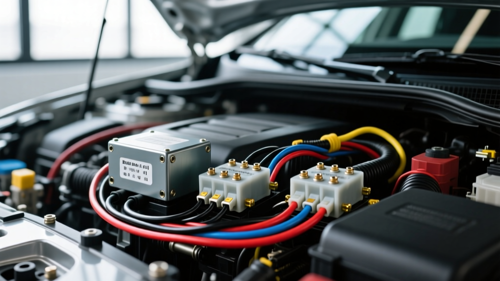
Introduction to HID Electrical Architecture
High-Intensity Discharge (HID) Xenon lighting systems require a precise electrical architecture to function safely and reliably. Unlike standard halogen bulbs that draw a steady resistive load, HID systems rely on complex ballasts and igniters that demand high inrush currents and generate massive voltage spikes. Understanding a complete HID wiring diagram is critical for avoiding melted OEM headlight switches, CANbus errors, and electromagnetic interference (EMI). This walkthrough dissects the standard 35W and 55W HID relay harness configuration, providing exact wire gauges, pinouts, and routing protocols for automotive applications.
Core Components of an HID Wiring Diagram
Before tracing the wires, you must understand the four primary nodes in any aftermarket or OEM HID conversion diagram:
- The Ballast (DC-AC Inverter): Converts 12V DC from the vehicle into ~85V AC to sustain the xenon plasma arc. A 35W ballast draws roughly 3.2A at steady state, while a 55W ballast draws ~5.0A.
- The Igniter: Generates the initial 23,000V to 25,000V pulse to strike the arc across the xenon gas gap. This is usually integrated into the base of a D2S/D2R bulb or housed in a separate inline module for AMP-style aftermarket kits.
- The Relay Harness: Bypasses the OEM headlight switch, using it only as a low-current trigger. This protects factory wiring from the 10A-15A startup inrush draw required by the ballast's capacitors.
- CANbus Decoders / PWM Filters: Necessary on modern vehicles (e.g., BMW, Dodge, Jeep, VW) that use Pulse Width Modulation (PWM) or bulb-out warning systems to monitor circuit resistance.
Step-by-Step HID Wiring Diagram Walkthrough
The following steps outline the physical routing and termination of a standard ISO mini-relay (Bosch pattern) HID harness. Always use GXL (Cross-Linked Polyethylene) wire for under-hood applications, as its 125°C temperature rating prevents insulation melting near exhaust manifolds or engine blocks.
Step 1: Main Power Feed (Pin 30)
Begin at the vehicle's battery positive terminal. Crimp a 14 AWG GXL red wire to a sealed ring terminal. Within 8 inches of the battery post, splice in an inline 20A ATC blade fuse holder. Route this 14 AWG wire through a split-loom corrugated tube directly to Pin 30 (the common power input) of the 4-pin automotive relay. Use adhesive-lined heat shrink (3:1 ratio) on all crimps to prevent moisture intrusion and galvanic corrosion.
Step 2: The Trigger Circuit (Pin 86)
The trigger wire activates the relay's internal electromagnet. Tap into the OEM headlight connector (e.g., H7, H11, 9005, or H13). The OEM positive wire will plug into the harness adapter, and the adapter's output will connect to Pin 86 via 16 AWG yellow GXL wire. Because this circuit only powers the relay coil (drawing less than 150mA), 16 AWG is sufficient and allows for easier routing through the firewall or headlight housing grommets.
Step 3: Grounding Protocol (Pin 85 & Ballast Grounds)
A poor ground is the leading cause of HID flickering and premature ballast failure. Run a 14 AWG black GXL wire from Pin 85 to a dedicated chassis ground point. Strip the paint down to bare metal using a wire wheel or sandpaper. Secure the M8 ring terminal with a stainless steel bolt and flange nut, torqued to 9-12 Nm. Coat the terminal in dielectric grease to prevent oxidation. The ballast case itself should also be bolted to metal chassis real estate to act as a heat sink and EMI shield.
Step 4: Load Output to Ballast (Pin 87)
Run a 14 AWG blue GXL wire from Pin 87 (the normally open output) to the 12V input plug of the HID ballast. Ensure the connector is a weather-sealed type, such as a Deutsch DT or a standard Weather-Pack, to withstand high-pressure car washes and engine bay steam.
HID Wiring Diagram Pinout & Specification Table
| Circuit Function | Wire Gauge & Type | Color Code | Relay Pin / Termination | Connector / Hardware |
|---|---|---|---|---|
| Main Power Feed | 14 AWG GXL | Red | Relay Pin 30 | Ring Terminal / 20A ATC Fuse |
| OEM Trigger Signal | 16 AWG GXL | Yellow | Relay Pin 86 | H7 / H11 / 9005 Adapter Plug |
| System Ground | 14 AWG GXL | Black | Relay Pin 85 | M8 Ring Terminal (Bare Metal) |
| Ballast Power Load | 14 AWG GXL | Blue | Relay Pin 87 | Weather-Pack / AMP Plug |
| High-Voltage Ignition | N/A (Shielded HV) | Silicone Boot | Ballast to Bulb | D2S / D2R / AMP Igniter |
Troubleshooting Common HID Wiring Failures
Even with a flawless HID wiring diagram, modern vehicle network systems can disrupt operation. Here is how to diagnose and fix the most common integration issues.
Flickering on Startup (PWM Signal Interference)
Symptom: The HID bulbs strobe, flicker, or fail to ignite fully on vehicles like the Dodge Ram, Jeep Wrangler, or VW Golf.
Cause: The vehicle's TIPM or BCM uses Pulse Width Modulation (PWM) to monitor the bulb circuit, sending rapid 12V pulses instead of a steady DC voltage. The HID ballast interprets this as a rapidly switching on/off command.
Fix: Install a PWM filter capacitor (typically a 4700µF 25V electrolytic capacitor) in parallel with the trigger wire at Pin 86. The capacitor absorbs the pulses and releases a steady DC voltage to the relay coil. Alternatively, use a dedicated digital CANbus decoder module.
Hyperflash or 'Bulb-Out' Dashboard Warnings
Symptom: The dashboard displays a headlight failure warning, and the turn signals (if integrated) hyperflash.
Cause: A 35W HID ballast draws significantly less steady-state current than a 55W halogen bulb. The vehicle's CANbus system detects the low amperage and assumes the bulb is blown.
Fix: Wire a 50W 6-ohm ceramic load resistor in parallel with the trigger circuit. Mount the resistor to a metal heat sink, as it will generate substantial heat during operation.
Radio Static and Electromagnetic Interference (EMI)
Symptom: AM/FM radio static, Bluetooth dropouts, or backup camera interference when the headlights are turned on.
Cause: The 23,000V ignition spike generates broadband RF noise. According to SAE J1113 standards for Electromagnetic Compatibility, unshielded high-voltage arcs will radiate EMI through the vehicle's wiring harness.
Fix: Ensure the ballast's metal housing is grounded to the chassis. Snap ferrite choke cores onto the 12V DC input wires as close to the ballast as possible to suppress high-frequency noise before it reaches the vehicle's main harness.
Authoritative References & Standards
When designing or modifying automotive lighting circuits, always adhere to established electrical standards to prevent fire hazards and component damage. For deeper technical specifications on relay footprints and contact ratings, refer to the Bosch Automotive Relays Technical Guide. For hands-on diagnostic procedures and multimeter testing of headlight switches and relay coils, the Haynes Headlight Relay Testing Guide provides excellent vehicle-specific flowcharts. Finally, ensure all high-voltage shielding and EMI suppression meet the rigorous testing protocols outlined in SAE J1113 to maintain the integrity of your vehicle's sensitive CANbus networks.