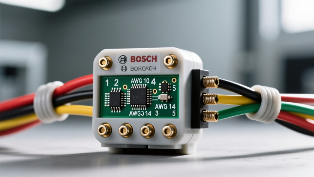
High-Current Electric Fan Relay Architecture
Upgrading to high-performance electric cooling fans, such as brushless SPAL or dual Maradyne setups, requires a robust electrical distribution network. The primary challenge in electric fan relay wiring is managing the massive inrush current, also known as Locked Rotor Amperage (LRA). While a standard 16-inch brushed electric fan may draw 12 to 15 amps during continuous operation, its initial startup surge can exceed 45 amps for several milliseconds. Factory wiring harnesses and standard OEM toggle switches are entirely incapable of handling this thermal and electrical load, leading to melted connectors, voltage drop, and premature switch failure.
To engineer a reliable electric fan relay wiring diagram, the high-current load path must be completely isolated from the low-current trigger circuit. This is achieved using heavy-duty ISO mini (Bosch-style) or maxi relays. By routing the main battery current through a dedicated high-amperage relay directly to the fan motor, the control circuit only needs to handle the relay coil's minimal draw (typically 150mA to 250mA). This architectural separation protects sensitive Engine Control Module (ECM) drivers and ensures the fan receives full system voltage (13.8V to 14.4V) under load, which is critical for maximizing the fan's cubic feet per minute (CFM) output.
DIN 72552 Standard Relay Pinout Specifications
The automotive industry universally adopts the DIN 72552 standard for relay terminal numbering. Understanding this electric fan relay wiring diagram pinout is mandatory for proper circuit assembly. Below is the technical specification for standard 4-pin (Single Pole Single Throw - Normally Open) and 5-pin (Single Pole Double Throw) configurations commonly used in cooling system upgrades.
| Terminal (Pin) | DIN Designation | Circuit Function | Wire Color (Typical SAE) | Wire Gauge (AWG) |
|---|---|---|---|---|
| 30 | Common (COM) | Main 12V+ Battery Power Input. Connects directly to the battery positive post or main distribution bus via a high-amperage fuse. | Red | 10 AWG or 8 AWG (TXL/GXL) |
| 87 | Normally Open (NO) | Load Output to Fan Motor (+). Power is delivered to this pin only when the relay coil is energized. | Pink or Blue | 10 AWG or 8 AWG (TXL/GXL) |
| 85 | Coil Ground | Relay Coil Ground. Connects to a clean chassis ground or directly to an ECM low-side driver output. | Black | 18 AWG or 16 AWG |
| 86 | Coil Power | Relay Coil Trigger (+). Receives 12V+ from a thermal switch, ignition source, or ECM high-side driver. | Dark Green | 18 AWG or 16 AWG |
| 87a | Normally Closed (NC) | 5-Pin Only. Carries power when the relay is de-energized. Rarely used in standard electric fan applications; often left isolated. | N/A | N/A |
When wiring the high-current load path (Pins 30 and 87), it is critical to use cross-linked polyethylene insulated wire (TXL, GXL, or SXL) rather than standard PVC primary wire. According to SAE J1128 specifications, GXL insulation offers superior resistance to under-hood thermal degradation and allows for a thinner insulation wall, improving flexibility in tight engine bays.
Wire Gauge (AWG) and Circuit Protection Sizing
Selecting the correct American Wire Gauge (AWG) prevents catastrophic harness fires and minimizes voltage drop. A voltage drop exceeding 0.5V across the power and ground circuits will significantly reduce fan motor RPM and cooling efficiency. The following chart outlines the minimum wire gauge and primary fuse requirements based on the maximum continuous amperage draw of the electric fan setup.
| Fan Configuration | Continuous Draw | LRA (Inrush) | Min. Power Wire (AWG) | Min. Ground Wire (AWG) | Main Fuse Rating (MAXI) |
|---|---|---|---|---|---|
| Single 11' Brushed Fan | 10A - 15A | ~35A | 12 AWG | 12 AWG | 25A |
| Single 16' Brushed Fan | 18A - 22A | ~55A | 10 AWG | 10 AWG | 40A |
| Single 16' Brushless Fan | 12A - 16A | ~20A (Soft Start) | 12 AWG | 12 AWG | 25A |
| Dual 11' Brushed Fans | 20A - 30A | ~70A | 8 AWG | 8 AWG | 50A |
| Dual 16' Brushed Fans | 36A - 44A | ~110A | 6 AWG | 8 AWG | 60A or 70A |
For all high-amperage connections, utilize open-barrel F-style crimps or closed-barrel copper ring terminals sealed with adhesive-lined, dual-wall heat shrink tubing. This prevents moisture intrusion and subsequent galvanic corrosion, which is a leading cause of high-resistance faults in cooling circuits.
PCM Integration and Inductive Kickback Protection
Modern vehicles utilize the Powertrain Control Module (PCM) to manage cooling fan operation based on coolant temperature, A/C head pressure, and vehicle speed. When integrating an aftermarket electric fan relay wiring diagram into a PCM-controlled system, you must identify whether the PCM utilizes a high-side driver (switching 12V+) or a low-side driver (switching ground).
If the PCM uses a low-side driver, Pin 86 of the relay is wired to a fused 12V ignition source, and Pin 85 is wired directly to the PCM's fan control output pin. When the PCM commands the fan ON, it completes the ground path, energizing the relay coil. However, when the PCM opens the circuit to turn the fan OFF, the collapsing magnetic field within the relay coil generates a high-voltage reverse spike (inductive kickback) that can exceed 100V. This spike will instantly destroy the PCM's internal solid-state transistor.
To prevent this, a flyback suppression diode (such as a 1N4001 or 1N4004) must be wired in parallel across the relay coil (Pins 85 and 86). The diode's cathode (marked with a silver stripe) must face the 12V+ source (Pin 86). This provides a safe recirculation path for the inductive spike, clamping the voltage to a safe ~0.7V and protecting the vehicle's sensitive electronic control modules. Many premium aftermarket relays, such as those from Hella or Tyco, feature this suppression diode or a high-ohm resistor built directly into the relay housing.
Dual Fan Series vs. Parallel Relay Logic
When wiring dual electric fans, you have two primary architectural choices: parallel operation or series operation (often used in factory setups for a 'low/high' speed function).
- Parallel Configuration: Both fans receive 12V+ simultaneously. This requires either two independent 40A relays (one for each fan) or a single heavy-duty 70A relay. Independent relays are preferred as they halve the current load per circuit, allowing the use of smaller 10 AWG wiring to each individual fan motor.
- Series/Parallel High-Speed Logic: In a factory-style dual-fan setup, three relays are used. For low speed, the fans are wired in series, splitting the 12V system (each fan sees 6V and runs at half speed). For high speed, the relays reconfigure the circuit into a parallel layout, delivering full 12V to both fans. This complex electric fan relay wiring diagram requires precise routing to prevent short circuits during the relay transition phase.
Voltage Drop Diagnostics and Failure Modes
Troubleshooting an electric fan relay circuit requires moving beyond simple test lights. A test light will illuminate even if the circuit suffers from severe voltage drop, giving a false sense of security. A digital multimeter (DMM) is mandatory for accurate diagnostics. Refer to this diagnostic decision tree when a fan fails to engage:
- Fan does not run, Relay does not click:
Measure voltage between Pin 86 and battery ground (should be 12V+). Measure continuity between Pin 85 and chassis ground. If both are present, the relay coil is internally open. Replace the relay. - Fan does not run, Relay clicks audibly:
The coil circuit is functional. Perform a dynamic voltage drop test across the high-current path. Place the DMM's red lead on the battery positive post and the black lead on the fan's positive terminal while the fan is commanded ON. A reading above 0.5V indicates high resistance in the power wire, fuse, or relay contacts (Pin 30 to 87). Carbon tracking inside the relay from repeated LRA arcing is a common failure mode here. - Fan runs slowly or cycles on and off rapidly:
This indicates a severe voltage drop on the ground side or an undersized wire gauge causing thermal breaker tripping. Measure the voltage drop from the fan's negative terminal directly to the battery negative post. If the reading exceeds 0.2V, clean the chassis ground point, upgrade the ground wire gauge, or add a dedicated ground bus bar.
For comprehensive guidance on selecting the correct relay harnesses and fusing blocks for high-amperage cooling systems, consult the Summit Racing Automotive Relay Wiring Guide, which provides excellent visual references for heavy-duty terminal crimping and harness loom routing. Proper execution of these technical specifications ensures your cooling system operates reliably under the most extreme thermal loads.