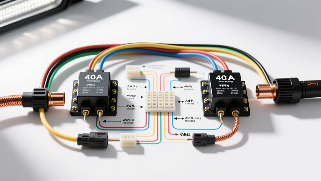
Why Standard Plug-and-Play Harnesses Fail in High-Amp Applications
Most off-road lighting kits include marginal wiring harnesses designed for 120W fog lights, not 240W+ LED light bars. When pushing 20+ amps continuously, undersized 18 AWG wires and cheap 30A micro-relays become severe fire hazards. Standard relay contacts can weld together under high inrush currents, and thin primary wires suffer from massive voltage drop, resulting in dimmed LEDs and melted insulation. This advanced light bar wiring diagram outlines a heavy-duty, dual-relay architecture integrated with a low-side PWM dimmer module, designed specifically for high-draw overland and off-road vehicles.
System Architecture & Component Selection
To build a reliable high-amperage lighting circuit, you must abandon automotive parts store relays and generic spool wire. We specify components based on strict automotive electrical standards:
- Relays: Use two ISO Mini 4-pin relays rated for 40A continuous (e.g., Tyco/Bosch V23234 series). Avoid 5-pin relays for lighting; the internal bridge between 87 and 87a can arc internally if wired incorrectly or subjected to vibration.
- Wire Specification: Use SAE J1128 GXL cross-linked polyethylene wire. GXL wire is rated for 125°C, allowing it to safely carry higher current densities than standard 85°C PVC primary wire without melting the insulation.
- Circuit Protection: Use MIDI or AMI fuses for the main 40A+ power lines. Standard ATO blade fuses are prone to terminal spreading and heat buildup at currents exceeding 30A.
- Terminals: Adhesive-lined heat shrink ring terminals with a copper barrel. Never use vinyl-insulated crimp terminals under the hood; the plastic sleeves melt and wick moisture via capillary action.
High-Amp Light Bar Wiring Diagram: Pinout & Routing
The following table details the exact pinout for a dual-relay setup where Relay A powers the left half of the light bar (or a secondary bar) and Relay B powers the right half. This splits the thermal load across two relays and allows for independent zone control if desired.
| Relay Pin | Function | Wire Gauge & Color | Routing & Termination Notes |
|---|---|---|---|
| 30 | Main Power Input | 10 AWG Red | Direct to battery positive via 40A MIDI fuse (within 6 inches of terminal). |
| 87 | Load Output | 10 AWG Red | Routes to light bar positive terminal. Use Deutsch DT 2-pin connector at the grille. |
| 85 | Relay Coil Ground | 14 AWG Black | Terminated to a dedicated chassis ground stud, not a shared factory bolt. |
| 86 | Trigger / PWM Input | 14 AWG Yellow | Connects to cabin switch, BCM upfitter output, or PWM MOSFET drain. |
Voltage Drop Calculation & AWG Sizing Matrix
Voltage drop is the silent killer of LED light bar performance. LEDs require a specific forward voltage; if the wiring harness drops 2 volts over a 15-foot run, the internal constant-current drivers will compensate by drawing more amperage, generating excess heat. The chart below assumes a 12.6V resting battery voltage and a maximum acceptable drop of 3% (0.38V) for sensitive LED drivers.
| Total Wire Length (Out & Back) | Current Draw (Amps) | Minimum AWG (GXL) | Voltage Drop at 12.6V |
|---|---|---|---|
| 10 Feet | 15A | 14 AWG | 0.26V (2.0%) |
| 15 Feet | 20A | 10 AWG | 0.30V (2.3%) |
| 20 Feet | 30A | 8 AWG | 0.38V (3.0%) |
| 25 Feet | 40A | 6 AWG | 0.40V (3.1%) |
Note: Always calculate total circuit length by doubling the physical distance from the battery to the light bar to account for the ground return path.
Integrating Low-Side PWM Dimming for LED Light Bars
Dimming a high-amp LED light bar using a standard variable resistor (rheostat) will result in immediate thermal failure. You must use Pulse Width Modulation (PWM). However, never apply a PWM signal directly to a mechanical relay coil (Pin 86). Rapidly switching a relay coil causes severe contact chatter, arcing, and inductive voltage spikes that will destroy your switchgear and vehicle CAN-bus.
The Correct PWM Architecture
- Main Power: The 40A mechanical relay handles the heavy lifting, acting as a simple ON/OFF contactor. Pin 86 receives a standard 12V trigger from the cabin.
- Low-Side Switching: Install a heavy-duty automotive PWM MOSFET module (rated for 60A+) on the ground side of the light bar. The light bar's negative terminal connects to the MOSFET's Drain, and the MOSFET's Source connects to the chassis ground.
- Flyback Protection: LED drivers contain large capacitors and inductive components. When the MOSFET switches off, the collapsing magnetic field generates a reverse voltage spike (back-EMF). You must solder a 1N5819 Schottky diode across the light bar's positive and negative terminals (cathode to positive, anode to negative) to safely recirculate this spike and protect the MOSFET.
For comprehensive solid-state relay and MOSFET integration guidelines, refer to the Littelfuse Automotive Relay Datasheets and application notes on inductive load suppression.
Grounding, Crimping, and Environmental Sealing
A wiring diagram is only as good as its physical terminations. The majority of off-road lighting failures occur at the ground ring terminal due to vibration and galvanic corrosion.
- Surface Prep: Remove all paint, powder coat, and primer from the chassis grounding point down to bare, shiny steel. Use a 2-inch sanding disc or a dedicated grounding bit.
- Corrosion Inhibition: Immediately after crimping and sealing the ring terminal, coat the bare metal and terminal with a zinc-flake spray or dielectric grease to prevent flash rust.
- Torque Specifications: An M6 (6mm) ground bolt should be torqued to 9-12 Nm (80-106 in-lbs). An M8 bolt requires 20-25 Nm. Under-torquing allows vibration to break the connection; over-torquing stretches the bolt, reducing clamping force over time.
- Crimp Profile: Use a hex-crimp die for non-insulated terminals and an indent-crimp die for adhesive-lined heat shrink terminals. The adhesive must melt and extrude from both ends of the sleeve to guarantee a watertight seal.
Advanced Troubleshooting Decision Tree
When a high-amp light bar system fails, use this diagnostic tree to isolate the fault without blindly replacing components.
Symptom: Light bar flickers rapidly at high RPM or over rough terrain
- Cause A: Relay coil voltage dropping below the 6V hold threshold due to a poor cabin trigger ground.
- Fix: Measure voltage at Pin 86 while the engine is revving. If it fluctuates, route a dedicated 14 AWG ground wire from Pin 85 directly to the battery negative, bypassing the chassis.
- Cause B: PWM frequency is too low (under 100Hz), causing visible flicker to the human eye or camera sensors.
- Fix: Adjust the PWM controller dip switches to output a frequency between 200Hz and 500Hz.
Symptom: Light bar turns on, but dims significantly after 5 minutes of use
- Cause A: Thermal throttling inside the light bar's internal LED drivers due to excessive voltage drop in the harness causing over-amping.
- Fix: Perform a voltage drop test across the entire positive and negative circuit while the lights are on and hot. If the combined drop exceeds 0.5V, upgrade the main power and ground wires by two AWG sizes.
- Cause B: Undersized relay contacts are heating up, increasing internal resistance.
- Fix: Use an infrared thermometer to check the relay casing. If it exceeds 80°C (176°F), replace with a higher-rated 50A or 60A relay, or parallel a second relay as outlined in the diagram above.
Symptom: Cabin switch or BCM upfitter circuit blows fuses immediately upon activation
- Cause: Inductive kickback from the relay coil destroying the BCM's internal solid-state switch, causing a dead short.
- Fix: Install a 1N4001 flyback diode directly across the relay socket terminals 85 and 86 (stripe facing Pin 86). This provides a safe path for the collapsing magnetic field, protecting sensitive vehicle electronics. Consult Painless Performance Wiring Manuals for specific BCM integration schematics and upfitter switch current limits.
Final System Validation
Before sealing the firewall grommet and zip-tying the harness, perform a bench test. Connect a 12V power supply capable of delivering 40A. Activate the circuit and measure the voltage directly at the light bar's Deutsch connector pins. You should read no less than 12.2V under full load. Verify the PWM dimmer operates smoothly across its entire range without causing audible buzzing from the relay or the light bar's internal capacitors. Once validated, loom the entire harness in split-loom tubing, secure it with UV-resistant cable ties every 8 inches, and route it away from exhaust manifolds and steering shafts.