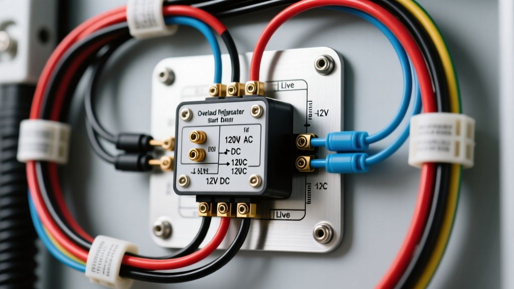
Mobile Refrigeration: Bridging Appliance and Automotive Electrical Systems
When diagnosing a failed cooling unit in a Class A motorhome, overland camper, or marine vessel, technicians frequently search for an overload refrigerator start relay wiring diagram to trace the compressor circuit. While residential appliance repair and automotive electrical systems are often treated as separate disciplines, the RV and marine sectors demand a hybrid expertise. Mobile refrigerators must withstand high-vibration environments, extreme voltage fluctuations, and marine-grade corrosion, all while utilizing compressor start mechanisms derived from both 120V AC residential designs and 12V/24V DC automotive architectures.
In this advanced technical deep dive, we will dissect the wiring diagrams, pin configurations, and overload protection mechanisms for both 120V AC RV refrigerators (such as Dometic and Norcold AC compressor models) and 12V DC mobile compressors (like the ubiquitous Secop/Danfoss BD series). Understanding the distinction between a mechanical Positive Temperature Coefficient (PTC) start relay and a modern solid-state Electronic Control Unit (ECU) is critical for accurate troubleshooting and safe, code-compliant mobile wiring.
120V AC RV Compressors: PTC Start Relays and Bimetallic Overloads
Many larger RVs and fifth wheels utilize 120V AC compressor-driven refrigerators. These units typically employ hermetically sealed compressors (often manufactured by Tecumseh, Embraco, or Secop) that require a start relay to engage the start winding and an overload protector to prevent thermal destruction during locked rotor conditions.
The Physics of the PTC Start Relay
Unlike older potential or current relays, modern RV refrigerators use a PTC (Positive Temperature Coefficient) thermistor as the start relay. When cold, the PTC disc exhibits low resistance (typically 2 to 10 ohms), allowing high current to flow through the compressor's start winding, generating the necessary phase-shifted magnetic field to initiate rotor movement. As current flows, the PTC heats up rapidly. Within a fraction of a second, its resistance spikes to near-infinity, effectively disconnecting the start winding while the run winding maintains operation. If the compressor fails to start and draw high Locked Rotor Amperage (LRA), the series-wired bimetallic overload protector will snap open, cutting power to the common terminal and preventing winding burnout.
120V AC Compressor Pinout and Wire Color Standards
When referencing an overload refrigerator start relay wiring diagram for a 120V AC RV unit, you will encounter a three-pin compressor terminal block. Per RVIA Best Practices and standard HVAC/R conventions, the terminals are labeled C, S, and R.
| Terminal | Designation | Internal Wire Color | Function & Relay Connection |
|---|---|---|---|
| C | Common | Black | Main power feed. Connects to 120V Hot (Black) via the Bimetallic Overload Protector. |
| R | Run | White | Run winding. Connects directly to 120V Neutral (White). |
| S | Start | Red or Orange | Start winding. Connects to the PTC Start Relay, which bridges to the Run terminal or Neutral. |
Wiring Note: The overload protector is physically mounted over the Common (C) pin to monitor the heat of the compressor shell and the current draw. When replacing a burnt PTC relay, always replace the overload protector simultaneously, as thermal fatigue compromises its snap-disc calibration.
12V/24V DC Mobile Compressors: The Electronic Control Unit (ECU)
In overland rigs, camper vans, and marine applications, 12V DC compressor refrigerators are the standard. The industry benchmark is the Secop (formerly Danfoss) BD35F and BD50F series. These compressors do not use a mechanical PTC start relay or a bimetallic overload. Instead, they utilize a sophisticated Electronic Control Unit (ECU) that acts as a solid-state start relay, inverter, and electronic overload protector.
The ECU converts 12V/24V DC into a three-phase AC signal to drive a brushless DC (BLDC) motor. It monitors back-EMF to determine rotor position, manages soft-start ramp-ups to minimize voltage drop on the vehicle's house battery bank, and instantly cuts power if it detects a locked rotor or excessive thermal load.
Secop BD Series ECU Terminal Specifications
Wiring a DC mobile fridge requires strict adherence to voltage drop limitations. According to SAE J1171 standards for marine and RV electrical systems, voltage drop on critical DC compressor circuits must not exceed 3%. Using undersized wire will cause the ECU's low-voltage cutoff to trigger prematurely, mimicking a failed start relay.
| ECU Terminal | Label | Function | Recommended AWG (up to 15ft run) |
|---|---|---|---|
| 1 | C (Common) | Thermostat signal return. Connects to thermostat switch. | 16 AWG (Signal wire) |
| 2 | T (Thermostat) | Thermostat signal input. Closes circuit to command start. | 16 AWG (Signal wire) |
| 3 | + (Positive) | Main 12V/24V DC Power Input. Must be fused. | 10 AWG (Tinned Copper) |
| 4 | - (Negative) | Main DC Ground. Must connect directly to house battery bus. | 10 AWG (Tinned Copper) |
| 5 | D (Diagnostics) | LED fault code output (flashes error codes). | 18 AWG (Optional) |
| 6 | S (Fan) | 12V Output to condenser fan (switched by ECU). | 16 AWG |
Advanced Installation and Overload Protection Integration
Whether you are wiring a 120V AC PTC relay circuit or a 12V DC ECU, mobile environments demand superior termination techniques. Vibration is the enemy of electrical continuity.
- Terminal Selection: Never use bare spade connectors on mobile compressor relays. Use nylon-insulated, heat-shrink ring terminals for threaded studs, or fully insulated female disconnects with detents for spade terminals. For 120V AC compressor pins, use 187-series (3/16') or 250-series (1/4') spades depending on the manufacturer.
- Crimping Standards: Use a ratcheting crimper calibrated for the specific AWG. A poorly crimped 10 AWG wire on a 12V DC ECU positive terminal will introduce resistance, generating heat that the ECU may misinterpret as an internal compressor overload.
- Corrosion Prevention: In marine and high-humidity RV environments, apply a dielectric grease (like NO-OX-ID A-Special) to the spade terminals before mating them to the PTC relay or ECU. This prevents galvanic corrosion which increases resistance and causes voltage drop.
- Overcurrent Protection: For 120V AC circuits, a 15A ceramic time-delay fuse or a D-curve miniature circuit breaker (MCB) is required to handle the brief LRA spike without nuisance tripping. For 12V DC Secop compressors, install a 20A ANL or MIDI fuse within 7 inches of the house battery positive terminal, per ABYC and NFPA 1192 standards.
Troubleshooting Decision Tree: Compressor Fails to Start
When the refrigerator fails to cool and the compressor remains silent, use this diagnostic sequence to isolate the relay, overload, or ECU.
Scenario A: 120V AC System (PTC Relay & Overload)
- Symptom: Compressor hums loudly for 3 seconds, then clicks off.
- Cause: The start winding is not engaging, causing the compressor to stall on LRA. The bimetallic overload protector snaps open to save the windings.
- Fix: Disconnect power. Remove the PTC relay. Shake it; if it rattles like a maraca, the internal ceramic disc has shattered from heat stress. Test the PTC with a multimeter; it should read between 2 and 15 ohms at room temperature. Replace the PTC and the overload protector.
Scenario B: 12V DC System (Secop ECU)
- Symptom: Compressor does not hum. The diagnostic LED on the ECU flashes 3 times, pauses, and repeats.
- Cause: According to the Secop BD Compressor Technical Handbook, 3 flashes indicate a motor start failure or a locked rotor. The ECU's internal electronic overload has tripped.
- Fix: Do not immediately condemn the ECU. First, check for voltage drop. Measure the DC voltage directly at the ECU's '+' and '-' terminals while the thermostat is calling for cooling. If voltage drops below 10.5V during the start attempt, the wiring gauge is insufficient or the battery bank is degraded. If voltage remains above 11.5V and the compressor still fails to start, the mechanical compressor is seized, or the ECU's internal MOSFET bridge has failed, requiring ECU replacement.
Conclusion
Mastering mobile refrigeration requires an understanding of both legacy mechanical relays and modern solid-state motor controllers. By referencing the correct overload refrigerator start relay wiring diagram for your specific mobile application, adhering to strict AWG sizing guidelines, and utilizing marine-grade termination methods, you can ensure reliable cooling in the most demanding off-grid and overland environments.