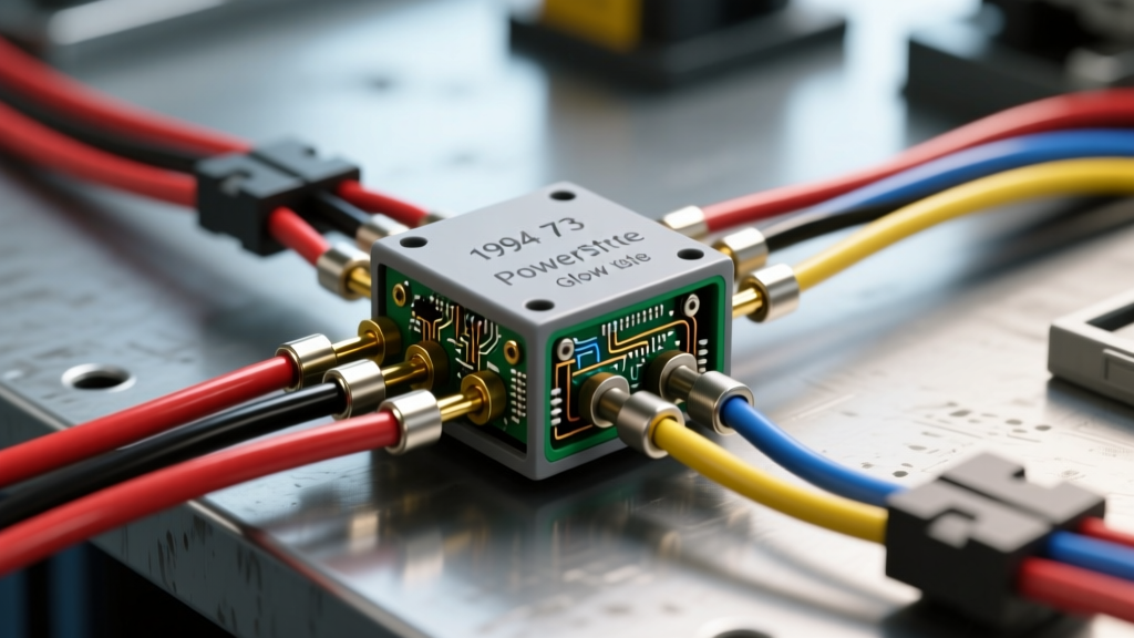
Understanding the 7.3L Powerstroke Glow Plug Relay System
The 7.3L Powerstroke diesel engine, produced from 1994 to 2003, relies on a robust glow plug system to achieve the cylinder temperatures necessary for cold-weather combustion. At the heart of this system is the Glow Plug Relay (GPR), a heavy-duty electromagnetic switch capable of handling up to 200 amps of continuous current during startup. When the relay fails, or when the factory wiring degrades, owners are left with hard-starting engines and excessive white smoke. Understanding the 7.3 powerstroke glow plug relay wiring diagram is critical for accurate diagnostics, proper replacement, and cost-effective upgrades.
Unlike standard automotive 12V relays used for lighting or horns, the 7.3L GPR utilizes heavy-gauge battery cables and a specialized Powertrain Control Module (PCM) ground circuit. This guide provides a comprehensive cost and tool requirements analysis for rewiring, replacing, and upgrading your 7.3L glow plug relay, ensuring you have the exact specifications needed to restore reliable cold-weather starting.
7.3 Powerstroke Glow Plug Relay Wiring Diagram & Pinout
The factory GPR wiring harness consists of four primary connections: two heavy-duty high-current posts and two low-current control spades. The PCM monitors Engine Oil Temperature (EOT) and Barometric Pressure (BARO) to determine how long to ground the relay coil, keeping the glow plugs active for anywhere from 1 to 120 seconds.
Terminal Pinout and Wire Specifications
| Terminal | Type | Wire Color (Typical) | AWG Size | Function & Voltage |
|---|---|---|---|---|
| Large Post 1 (Input) | 13mm Stud | Black / Red (Fusible Link) | 2 AWG or 4 AWG | Constant 12V+ from Batteries via Fusible Link |
| Large Post 2 (Output) | 13mm Stud | Black / Red | 2 AWG or 4 AWG | Switched 12V+ to Left/Right Glow Plug Bus Bars |
| Small Spade 1 (Trigger) | 1/4" Blade | Red/Yellow (OBS) or Red (SD) | 14 AWG | 12V+ Ignition Source (Key in RUN/START) |
| Small Spade 2 (Ground) | 1/4" Blade | Pink/White or Yellow/Black | 14 AWG | PCM Controlled Ground Path |
Note: Wire colors may vary slightly between the OBS (1994-1997) and Super Duty (1999-2003) chassis harnesses, but the functional pinout remains identical. Always verify with a multimeter. For detailed primary cable standards, refer to SAE J1128 Low Tension Primary Cable specifications.
Tool Requirements for GPR Wiring & Replacement
Replacing the relay is a straightforward bolt-on job, but properly diagnosing the wiring and upgrading the heavy-gauge lugs requires specialized automotive electrical tools. Attempting to crimp 2 AWG wire with standard pliers will result in high-resistance connections that melt under the 200-amp load.
Essential Diagnostic & Installation Tools
- Digital Multimeter (DMM): Required for voltage drop testing and verifying the PCM ground signal. A true-RMS meter like the Fluke 87V is recommended for accurate readings in high-EMI diesel environments.
- Heavy-Duty Wire Crimper: Must accommodate 4 AWG to 1/0 AWG terminals. Hydraulic crimpers or ratcheting heavy-gauge crimpers (e.g., Knoweasy or Titan) are mandatory for the main power posts.
- Wire Strippers & Cutters: Capable of cleanly stripping 2 AWG welding cable and 14 AWG primary wire without nicking the copper strands.
- Adhesive-Lined Heat Shrink & Torch: 3:1 shrink ratio tubing with internal sealant to prevent moisture intrusion and copper oxidation at the heavy lugs.
- Socket Set & Torque Wrench: 13mm deep sockets for the large relay posts. A 1/4-inch drive torque wrench is necessary to tighten the nuts to 80-100 in-lbs (approx. 9-11 Nm) without snapping the threaded studs.
- Dielectric Grease: Applied to the small control spades and bus bar connections to prevent galvanic corrosion.
Cost Breakdown: OEM vs. Aftermarket & Wiring Materials
The cost to repair or upgrade the 7.3 powerstroke glow plug relay wiring varies significantly based on whether you choose OEM Motorcraft components, heavy-duty aftermarket alternatives, or modern solid-state upgrades. Below is a realistic cost analysis for a complete relay and wiring refresh.
| Component / Material | OEM / Standard Option | Heavy-Duty / Upgrade Option | Estimated Cost (USD) |
|---|---|---|---|
| Glow Plug Relay | Motorcraft SW-6189 | White Rodgers 586-902 (Marine Grade) | $45.00 - $85.00 |
| Solid-State Contactor | N/A | Diesel Site or GPR400 Upgrade | $110.00 - $140.00 |
| Heavy Gauge Cable (2 AWG) | Pre-made harness | Custom 1/0 AWG Welding Cable | $15.00 - $30.00 |
| Terminals & Heat Shrink | Standard Copper Lugs | Tinned Copper with 3:1 Adhesive Shrink | $10.00 - $20.00 |
| PCM Protection Diode | Factory Harness Diode | Inline 6A 1000V Diode Mod | $5.00 - $15.00 |
Total Estimated Cost: A basic replacement using a White Rodgers relay and standard tools will cost around $60. A complete heavy-duty wiring upgrade with custom 1/0 AWG cables and a solid-state contactor will range from $160 to $200. For official OEM part numbers and harness diagrams, consult the Motorcraft technical resource center.
Step-by-Step Wiring & Diagnostic Procedure
Before purchasing parts, you must verify if the relay is faulty or if the issue lies within the wiring harness. The most common misdiagnosis is replacing a perfectly good relay when the actual failure is a blown PCM protection diode or a degraded fusible link.
1. The Voltage Drop Test (Testing the Heavy Circuit)
Set your multimeter to DC Volts. Place the red probe on the large input post (constant 12V) and the black probe on the large output post (to the glow plugs). Have an assistant turn the key to the RUN position (or unplug the EOT sensor to force the PCM to activate the relay for 2 minutes).
Passing Spec: The voltage drop across the relay contacts should be less than 0.10V.
Failing Spec: A reading of 0.50V or higher indicates severely pitted internal contacts or high resistance in the factory 4 AWG cables. If the input post reads less than 12.0V with the engine off, your fusible link or battery cables are degraded.
2. Verifying the PCM Ground and Trigger Circuit
If the heavy posts have 12V but the relay does not click, test the small spades.
First, check the trigger spade with the key ON; it should read battery voltage (approx 12.4V).
Next, connect your multimeter's red probe to the positive battery terminal and the black probe to the ground spade. When the PCM activates the relay, the meter should read 12V, confirming the PCM is providing the ground path. If the trigger wire has 12V but the PCM ground is missing, the relay coil is open, or the PCM driver is faulty.
3. The Infamous PCM Diode Failure
In the 7.3L Powerstroke wiring harness, Ford installed a protective diode in the glow plug relay trigger wire circuit to prevent voltage spikes from the relay coil from frying the PCM. When this diode blows (opens), it completely interrupts the 12V trigger signal to the relay. The glow plugs will never turn on, and the 'Wait to Start' light may behave erratically. Splicing a standard 6-Amp 1000V rectifier diode (like a 6A10) into the trigger wire, with the stripe facing the relay, bypasses the blown factory diode for under $5 and restores full functionality.
Real-World Failure Modes & Upgrading to Solid-State
The mechanical contacts inside the factory GPR eventually arc and pit due to the massive 200-amp inrush current of the glow plugs. This arcing generates intense heat, which often melts the plastic insulator between the large posts or degrades the factory 4 AWG wire lugs, causing a voltage drop that starves the glow plugs of the amperage they need to heat the cylinders.
To permanently resolve this, many 7.3L owners are upgrading to a Solid-State Contactor. These units use high-amperage MOSFETs or thyristors instead of mechanical moving parts. They generate zero internal heat, feature zero voltage drop across the main terminals, and are completely immune to the contact pitting that destroys mechanical relays. When installing a solid-state unit, the 7.3 powerstroke glow plug relay wiring diagram remains exactly the same, but it is highly recommended to upgrade the factory 4 AWG cables to 1/0 AWG flexible welding cable with adhesive-lined heat shrink to ensure the wiring harness can support the flawless current delivery of the new contactor.
By understanding the precise wiring topology, utilizing the correct heavy-gauge crimping tools, and addressing common failure points like the PCM diode, you can restore your 7.3L Powerstroke's cold-weather starting reliability for a fraction of the cost of a dealership diagnostic fee.