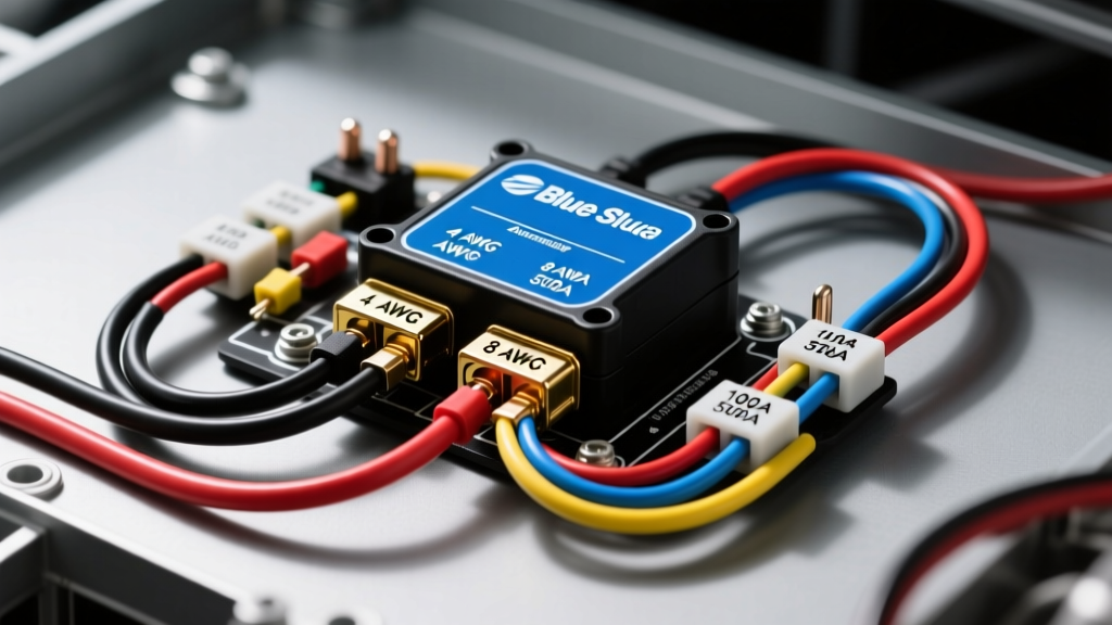
Executing the Dual Battery Upgrade: Blue Sea ACR Architecture
Upgrading your overland rig, camper van, or marine vessel with a dual battery system is one of the most impactful modifications you can make. When isolating your starting battery from your auxiliary house loads, the Blue Sea automatic charging relay wiring diagram serves as the gold standard for 12V DC power management. Unlike manual isolator switches or diode-based separators that introduce a 0.6V voltage drop, an Automatic Charging Relay (ACR) like the Blue Sea 7610 (120A) or 7622 (220A) uses a heavy-duty internal contactor to parallel the batteries only when a charging source is detected. This guide details the exact execution of the wiring diagram, focusing on AWG sizing, ignition sense routing, and critical failure mode prevention for your upgrade project.
Pre-Installation: Alternator Sizing and Battery Chemistry Warnings
Before cutting a single length of wire, you must evaluate your vehicle's charging system. When the ACR detects a charging voltage (typically 13.6V for 30 seconds), it closes the internal contactor, bridging the start and house batteries. If your auxiliary AGM or Lead-Acid battery is deeply discharged, the inrush current can easily exceed 200A. According to SAE J1171 standards for automotive electrical systems, stock alternators are not designed to sustain maximum output for extended periods, and severe inrush spikes can blow the internal rectifier diodes.
Critical Lithium Warning: If your upgrade project utilizes Lithium Iron Phosphate (LiFePO4) batteries, a standard ACR is highly discouraged. LiFePO4 batteries have near-zero internal resistance. When the ACR closes, the alternator will dump maximum amperage into the lithium bank, potentially melting wiring or triggering the Battery Management System (BMS) to disconnect due to over-current protection. For lithium upgrades, bypass the ACR entirely and use a DC-DC battery charger. The Blue Sea ACR wiring diagram outlined below is strictly engineered for Lead-Acid, AGM, and Gel cell chemistries.
Understanding the 7610 ACR Terminal Pinout
The Blue Sea 7610 ACR features four primary connection points. Miswiring the small control terminals is the most common cause of ACR failure in DIY modifications.
- Large Stud A: Primary Start Battery Positive (12V+)
- Large Stud B: Auxiliary House Battery Positive (12V+)
- Small Terminal 1 (Ignition Sense): Optional 12V+ input. When energized, it lowers the combine threshold to 12.35V to account for voltage drop when heavy vehicle accessories are running.
- Small Terminal 2 (Ground): Case and coil ground reference. Must be tied to a clean chassis ground, not daisy-chained to a battery negative.
Step-by-Step Wiring Diagram Execution
Follow these steps to ensure your dual battery system meets ABYC E-11 and SAE DC wiring standards for safety and voltage drop mitigation.
Step 1: Routing the Heavy Gauge Positive Cables
Measure the distance from the Start Battery positive terminal to the ACR Stud A, and from the House Battery positive to Stud B. For runs under 10 feet, use 1/0 AWG pure copper stranded wire. For runs between 10 and 20 feet, upgrade to 2/0 AWG to maintain a voltage drop below 3%. Crimp the terminals using a hex-crimper and seal them with adhesive-lined dual-wall heat shrink to prevent galvanic corrosion under the hood. Route the cables through split-loom tubing to protect against chassis abrasion and high engine bay temperatures.
Step 2: Installing Inline Circuit Protection
The ACR itself does not contain internal fusing. You must install a 150A ANL or Class T fuse on both the Start Battery positive cable and the House Battery positive cable. Per SAE guidelines, these fuses must be mounted within 7 inches of the battery positive terminal to protect the entire cable run in the event of a dead short against the chassis.
Step 3: Wiring the Ignition Sense and Ground Control
Splice into an ignition-switched 12V+ circuit in the engine bay (such as the fuel pump relay trigger or an auxiliary upfitter switch) using 16 AWG yellow wire. Connect this to Terminal 1. This ensures the ACR combines the batteries even if the alternator output dips below 13.0V while running high-draw accessories like a winch or off-road lighting array. For Terminal 2, run a 10 AWG black wire to a dedicated, bare-metal chassis ground point. Use a star washer to bite through the paint and ensure a zero-ohm ground reference; a poor ground will cause the ACR coil to chatter and rapidly destroy the internal contacts.
Step 4: Torquing the Main Studs
Place the 1/0 AWG ring terminals onto Studs A and B. Blue Sea Systems specifies a torque rating of 120 in-lbs (10 ft-lbs) for the 5/16" stainless steel nuts. Under-torquing leads to micro-arcing and localized heat buildup, while over-torquing can strip the brass threads embedded in the contactor block.
Wire Gauge, Fuse, and Torque Specifications
| Component / Connection | Wire Gauge (AWG) | Wire Color Code | Protection / Torque Spec |
|---|---|---|---|
| Start Battery to Stud A | 1/0 AWG (up to 10ft) | Red (Primary B+) | 150A ANL Fuse (Max 7" from post) |
| House Battery to Stud B | 1/0 AWG (up to 10ft) | Red (Secondary B+) | 150A ANL Fuse (Max 7" from post) |
| Terminal 2 (Coil Ground) | 10 AWG | Black (Ground) | Ring terminal to bare chassis |
| Terminal 1 (Ignition Sense) | 16 AWG | Yellow (Switched 12V+) | 5A Inline ATO Fuse |
| Main Studs A & B Nuts | N/A | N/A | 120 in-lbs (10 ft-lbs) |
Troubleshooting Common ACR Failure Modes via LED Diagnostics
The Blue Sea 7610 features an integrated bi-color LED that communicates the internal state of the relay. Use this decision tree to diagnose your dual battery upgrade if the house bank is failing to charge.
LED is Solid Green (Combined)
Symptom: The relay is closed, bridging both batteries. However, a multimeter shows a 0.5V difference between Stud A and Stud B. Fix: This indicates severe voltage drop across the internal contactor pads due to carbon tracking or oxidation. The contactor is failing to make full surface contact. The ACR must be replaced; internal components are not user-serviceable.
LED is Flashing Green (Combining Pending)
Symptom: The ACR has detected 13.0V+ on one battery but is waiting out the 2-minute delay timer before closing. Fix: This is normal operation. If it flashes indefinitely without ever turning solid green, check the ground wire on Terminal 2. A high-resistance ground prevents the internal coil from generating enough magnetic force to pull the contactor fully closed.
LED is Solid Red (Isolated / Over-Temp)
Symptom: The alternator is running, but the ACR remains open and the LED is red. Fix: The ACR has entered thermal protection mode. This happens when the inrush current from a dead house battery exceeds the 120A rating for an extended period, causing the internal bimetallic strip to trip. Disconnect the house battery load, allow the ACR to cool for 15 minutes, and investigate why the auxiliary bank was deeply discharged below 10.5V.
LED is Off (No Power)
Symptom: No illumination, batteries are isolated. Fix: Verify voltage at both large studs. If Stud A has 12.6V but the LED is off, check the 150A ANL fuse on the start battery side. The ACR requires voltage on at least one main stud to power the internal logic board and LED indicator.
Final Upgrade Verification
Once the physical wiring is complete, start the vehicle and let it idle. Monitor the voltage at both battery terminals using a digital multimeter. You should see the start battery rise to ~14.2V. Within 30 to 120 seconds, you will hear a distinct, heavy 'clunk' from the engine bay as the contactor engages. At this moment, the house battery voltage should instantly jump to match the alternator output (within 0.1V, accounting for minor wire resistance). Turn off the engine. Within 30 seconds, the ACR will detect the voltage drop below 12.35V, open the contactor, and isolate the batteries, ensuring your auxiliary lighting, fridge, and camp accessories never strand you with a dead crank battery.