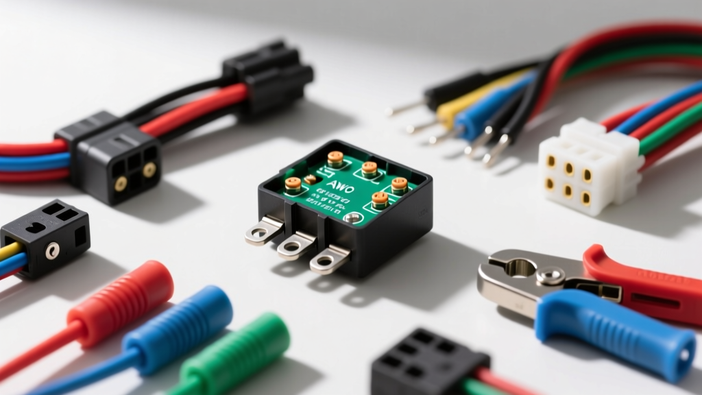
Why Factory Wiring Fails Modern LED Headlight Upgrades
Upgrading from factory halogen bulbs to high-output LED headlight assemblies is one of the most impactful nighttime driving modifications you can make. However, simply plugging an LED bulb into a factory H4, H11, or 9005 connector is a recipe for electrical gremlins, melted housings, and severe voltage drop. To do this correctly, you need a dedicated LED wiring diagram that utilizes a heavy-duty relay harness. This guide provides a comprehensive, expert-level breakdown of a universal 4-pin relay wiring configuration designed specifically for high-draw LED and HID headlight upgrades.
Factory headlight wiring was engineered for the steady, predictable resistance of a 55W halogen filament. Over a decade or more, the copper strands inside factory looms oxidize, increasing resistance. Furthermore, modern vehicles utilize Pulse Width Modulation (PWM) to monitor bulb health. When you introduce an LED driver—which draws significantly less amperage or features a massive initial inrush current—the Body Control Module (BCM) interprets this as a blown bulb or a short circuit. By implementing a standalone relay harness, you bypass the factory wiring for the heavy current load, using the factory wire strictly as a low-amperage trigger signal.
The Core 4-Pin Relay LED Wiring Diagram Breakdown
The backbone of this modification is the standard Bosch-style 4-pin automotive relay. Understanding the internal coil and switch mechanics is critical before cutting or splicing any wires. According to the Littelfuse Automotive Relay Application Guide, a standard 12V 40A relay features an electromagnetic coil that requires roughly 150mA to 200mA to close the high-current contactor.
| Relay Pin | Function | Wire Color (Standard) | AWG Size | Routing Destination |
|---|---|---|---|---|
| Pin 30 | Common / 12V+ Input | Red | 12 AWG | Direct to Battery Positive (via 30A Maxi-Fuse) |
| Pin 85 | Coil Ground | Black | 12 AWG | Dedicated Chassis Ground (Star Washer) |
| Pin 86 | Coil Trigger (12V+) | White | 16 AWG | Tapped to Factory Headlight Positive Wire |
| Pin 87 | Normally Open (Output) | Yellow | 12 AWG | Positive Input to LED Headlight Driver |
When the factory headlight switch is turned on, 12V travels down the factory wire to Pin 86. This energizes the coil (grounded via Pin 85), creating a magnetic field that pulls the internal contactor down. This connects Pin 30 (heavy battery power) to Pin 87, sending a massive, unimpeded flow of 12V+ directly to your new LED headlights.
Step-by-Step Headlight Upgrade Wiring Execution
Step 1: Battery and Fuse Integration
Never tap into the factory fuse box for the main power feed of an LED relay harness. The inrush current of LED capacitors can spike momentarily, causing nuisance trips if shared with sensitive ECU circuits. Run a dedicated 12 AWG SAE J1128 compliant primary wire directly from the battery positive terminal. Install a 30A Maxi-Fuse within 8 inches of the battery post. This complies with ABYC and SAE standards for overcurrent protection, ensuring that if the wire chafes against the chassis, the fuse blows before the wire melts and starts an engine bay fire.
Step 2: The Trigger Wire Tap
Locate the factory headlight connector (e.g., H4 9003). Identify the low-beam positive wire using a digital multimeter. With the factory harness disconnected, probe the terminals while an assistant turns on the low beams. Once identified, use a parallel splice connector or carefully strip back 3/8 inch of insulation to solder your 16 AWG white trigger wire. Seal the connection with adhesive-lined dual-wall heat shrink to prevent moisture ingress and subsequent galvanic corrosion.
Step 3: Grounding Strategy and Avoiding Ground Loops
The most common point of failure in aftermarket LED wiring diagrams is poor grounding. Do not ground the relay coil (Pin 85) or the LED driver negative wire to painted sheet metal or thin bracketry. Locate a thick, unpainted chassis bolt or engine block location. Use a self-tapping grounding screw with a star washer to bite through any surface oxidation. Coat the terminal in dielectric grease after tightening to 15 lb-ft of torque to block oxygen and water.
Overcoming PWM Flicker and CANBUS Errors
If you are upgrading a 2014+ Ram, 2019+ Silverado, or modern Jeep, your vehicle likely uses PWM (Pulse Width Modulation) to power the headlights. Instead of sending a steady 12V, the BCM rapidly switches the voltage on and off (often between 400Hz and 2000Hz) to dim the bulb or monitor the circuit. Because a relay coil is an inductive load, PWM signals will cause the relay to chatter violently, resulting in severe strobe effects from your LEDs.
The Anti-Flicker Capacitor Solution
To smooth out the PWM signal before it hits Pin 86 of your relay, you must install an anti-flicker module or a high-capacity electrolytic capacitor (typically 4700µF to 10000µF, rated for 16V or higher). Wire the capacitor in parallel with the trigger wire and ground. The capacitor absorbs the rapid voltage drops, providing a steady voltage curve to keep the relay coil fully saturated.
Blocking Diodes for High/Low Beam Backfeed
In dual-filament setups (like H4), upgrading to a relay harness can cause a 'backfeed' issue where both low and high beams stay on simultaneously. This happens because current travels backward through the dashboard high-beam indicator bulb, finding a path to ground through the low-beam relay coil. To fix this, solder a 1N5408 (3A 1000V) rectifier diode inline on the high-beam trigger wire, with the silver stripe facing toward the relay. This acts as a one-way check valve, completely eliminating backfeed.
Wire Gauge, Terminal, and Connector Specifications
Using the correct wire and terminals is non-negotiable for high-current automotive lighting. Referencing the SAE J1128 Low Tension Primary Cable Standard, below are the strict specifications for your harness build.
| Component | Specification | Tooling Required | Failure Mode if Ignored |
|---|---|---|---|
| Main Power/Ground | 12 AWG Stranded Copper (SGT) | Heavy-Duty Ratcheting Crimper | Voltage drop, melted insulation, fire |
| Trigger Wire | 16 AWG Stranded Copper (TXL) | Standard Ratcheting Crimper | Signal loss, relay chatter |
| Battery Terminal | #10 Ring Terminal (Heat Shrink) | Crimp & Heat Gun | Loose connection, arcing, battery drain |
| LED Connection | AMP Superseal 1.5 or Deutsch DT | Open-Barrel Crimper / Pin Tool | Moisture ingress, LED driver failure |
When terminating connections for the LED pigtails, avoid cheap, stamped closed-barrel terminals. Invest in open-barrel crimps and the proper Aptiv Metri-Pack or Deutsch crimping tools. A proper open-barrel crimp creates a gas-tight mechanical bond that will pass a 40-pound pull test, ensuring the connection survives years of engine bay vibration and thermal cycling.
Troubleshooting Common LED Relay Failures
Even with a perfect LED wiring diagram, real-world variables can cause issues. Use this decision tree to diagnose problems rapidly:
- Symptom: Relay clicks, but LEDs do not turn on.
Cause: Voltage drop on Pin 30 or Pin 87, or blown inline Maxi-Fuse.
Fix: Perform a voltage drop test across the fuse and the power wire while the circuit is under load. A reading above 0.2V indicates high resistance or a bad crimp. - Symptom: LEDs strobe or flicker rapidly when engine is running.
Cause: Alternator ripple current or PWM interference from the BCM.
Fix: Install a 4700µF smoothing capacitor on the trigger wire (Pin 86) or inline on the LED 12V+ feed to absorb AC ripple. - Symptom: Headlights stay on for 5-10 seconds after turning the switch off.
Cause: Residual capacitance in the LED driver combined with a high-resistance ground on Pin 85.
Fix: Improve the relay ground connection. Sand the chassis paint down to bare, shiny metal and re-secure the star washer ground.
Final Verification and Testing
Before zip-tying the harness and reassembling the front bumper or grille, perform a comprehensive functional test. Turn on the low beams and measure the voltage directly at the LED driver input pins. You should see no less than 13.2V with the engine idling (alternator charging at ~14.2V). Cycle the high beams, flash the passing lights, and turn on the fog lights to ensure no cross-circuit backfeed is occurring. By following this exact LED wiring diagram and adhering to strict AWG and crimping standards, your headlight upgrade will deliver brilliant, flicker-free illumination for the life of the vehicle.