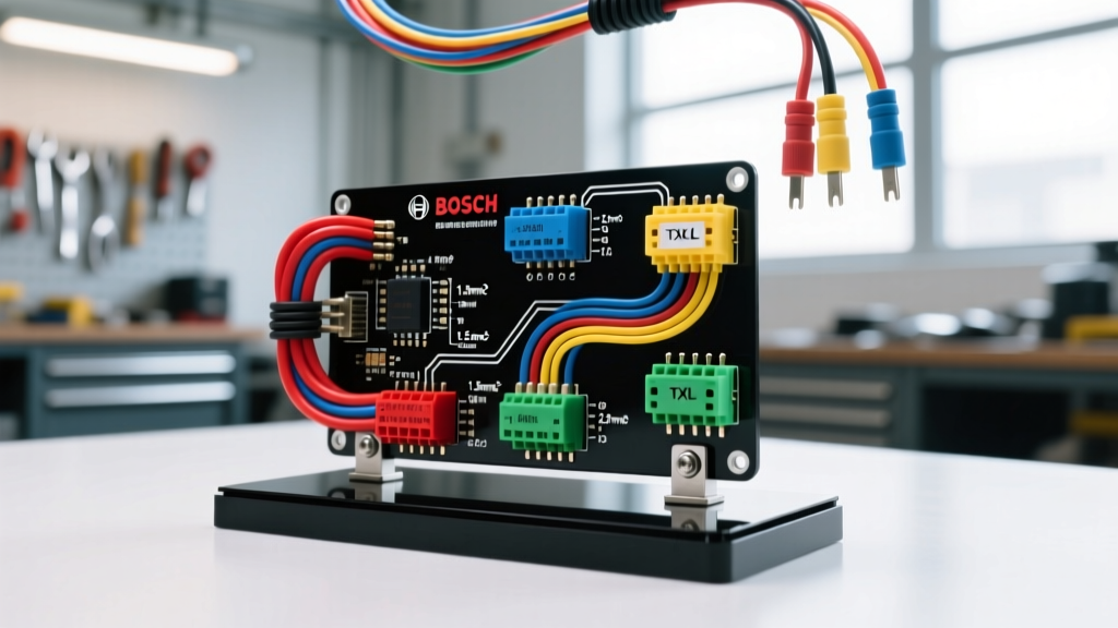
Why Centralize Your Motorsport Electrical System?
In high-performance motorsport environments, electrical reliability is just as critical as suspension geometry or engine tuning. A dedicated race car relay board serves as the central nervous system for high-current accessories, moving heavy electrical loads out of the driver's cockpit and into a sealed, serviceable, and vibration-dampened enclosure. By utilizing a centralized board, your cockpit switches only handle low-amperage signal currents (typically under 2A), drastically reducing the risk of switch overheating, melting, or catastrophic fire in the cabin.
This practical installation guide details how to design, crimp, and mount a professional-grade race car relay board using Bosch-style ISO mini relays, MIL-SPEC TXL wiring, and environmentally sealed connectors.
Essential Components for a Race Car Relay Board
Before cutting a single wire, you must source components capable of surviving extreme chassis vibration, under-hood heat cycles, and exposure to water and fuel. Standard auto-parts store components will fail prematurely in a race environment.
Selecting the Right Relays and Fuses
The industry standard for motorsport switching is the Bosch ISO Mini 4-pin and 5-pin relay. According to Bosch Mobility Solutions, these relays feature a 30A/40A continuous switching capacity and robust internal contact springs that resist high-G shock loads. For circuit protection, avoid standard glass fuses; instead, use ATO/ATC blade fuses for individual branch circuits and high-amperage MIDI or ANL fuses for the main power feed.
Wiring and Connector Specifications
Race cars require cross-linked polyethylene insulated wire, specifically TXL or GXL, which meets the SAE J1128 Standard for high-temperature resistance and thin-wall construction. For connectors, the TE Connectivity Deutsch DT Series is mandatory. These thermoplastic connectors utilize silicone rear wire seals and internal wedge locks to prevent terminal back-out under severe vibration.
| Circuit Function | Typical Load | Wire Gauge (TXL) | Fuse Rating | Relay Type |
|---|---|---|---|---|
| Main Ignition / ECU | 15A - 25A | 12 AWG | 30A ATO | 4-Pin (SPST) |
| Electric Fuel Pump | 20A - 30A | 10 AWG | 40A ATO | 4-Pin (SPST) + Diode |
| Dual Cooling Fans | 35A - 45A | 8 AWG | 50A MIDI | 4-Pin (SPST) x2 |
| LED Light Bar / Aux | 10A - 15A | 14 AWG | 20A ATO | 4-Pin (SPST) |
| Cockpit Signal Feed | 1A - 3A | 18 AWG | 5A ATO | N/A (Signal Only) |
Step-by-Step Race Car Relay Board Installation
Step 1: Layout and Mechanical Mounting
Construct your board base from 1/8-inch (3mm) 6061-T6 aluminum. Layout the relays and fuse blocks to ensure high-current paths are as short as possible. Crucial Motorsport Tip: Never bolt the board directly to the chassis or firewall. High-frequency engine harmonics will crack solder joints and loosen crimps. Mount the board using M6 rubber isolation bushings (often called Lord mounts) to decouple the board from chassis resonance. Ensure the main power feed uses a heavy-duty 6 AWG or 4 AWG battery cable terminated with a heavy-gauge ring terminal, torqued to 12-15 Nm to prevent arcing.
Step 2: Crimping and Harness Construction
Proper crimping is where most amateur race car builds fail. For Deutsch DT connectors, use an open-barrel crimp tool specifically calibrated for 12-18 AWG solid wire crimps. Strip exactly 5/32-inch of insulation. The crimp must pass the 'pull test'—yanking the wire firmly by hand should yield no movement.
- Pin 30 (12V+ In): Fed directly from the main fused bus bar. Use Red 12 AWG TXL.
- Pin 87 (12V+ Out): The high-current output to the accessory (e.g., fuel pump). Use Yellow 12 AWG TXL.
- Pin 85 (Ground): Tied to the central chassis star-ground point. Use Black 16 AWG TXL.
- Pin 86 (Switched Signal): Fed from the cockpit toggle switch. Use Blue 18 AWG TXL.
Secondary Retention: Once the crimped pins are inserted into the Deutsch housing, you must insert the orange or yellow plastic wedge lock. This wedge physically blocks the retention tangs from compressing, making it impossible for the pin to back out during a race.
Step 3: Routing High-Current vs. Signal Wires
Electromagnetic Interference (EMI) can cause erratic ECU behavior or false sensor readings. When routing the harness from the race car relay board, physically separate the high-current load wires (Pin 87) from the low-voltage signal wires (Pin 86 and ECU sensor wires). Maintain at least a 3-inch separation, or cross them at strict 90-degree angles. Wrap the entire harness in Tesa 51036 PET cloth tape to protect against abrasion and heat, avoiding cheap vinyl electrical tape which melts and leaves adhesive residue in engine bays.
Handling Inductive Loads and Flyback Voltage
When wiring inductive components like electric fuel pumps, cooling fans, or starter solenoids to your relay board, you must address flyback voltage. When the relay opens (turns off), the collapsing magnetic field in the motor generates a massive reverse voltage spike that can arc across the relay contacts, eventually welding them shut or frying sensitive solid-state ECU drivers sharing the same ground plane.
The Fix: Install a 1N5408 flyback diode across the relay coil terminals (Pin 85 and Pin 86), with the cathode (silver stripe) facing the positive signal feed. Alternatively, use relays with built-in suppression resistors or diodes, denoted by specific Bosch part numbers ending in 'Z' or 'D'.
Real-World Troubleshooting and Vibration Failures
Even meticulously built race car relay boards can experience faults. Here is a diagnostic decision tree for common motorsport electrical issues:
- Symptom: Relay clicks rapidly and erratically under heavy engine load.
Cause: Voltage drop on the ground circuit (Pin 85) or signal feed (Pin 86).
Fix: Perform a voltage drop test under load. Place multimeter probes on the battery negative terminal and the relay Pin 85 terminal. A reading above 0.1V indicates a poor star-ground connection or undersized ground wire. - Symptom: Accessory works cold but shuts off after 10 minutes of racing.
Cause: Thermal overload due to high resistance in the crimp joint.
Fix: Inspect the Deutsch connector pins. If the copper strands were trimmed during stripping, or if the wrong crimp die was used, resistance increases, generating heat. Cut back the wire and re-crimp using the correct open-barrel die. - Symptom: Fuel pump relay contacts weld shut, pump runs with ignition off.
Cause: Missing flyback diode on an inductive load causing contact arcing.
Fix: Replace the damaged Bosch relay, install a 1N5408 suppression diode, and upgrade the main feed fuse to handle the locked-rotor amperage (LRA) spike of the pump.
By adhering to SAE wiring standards, utilizing environmentally sealed connectors, and isolating the board from chassis harmonics, your custom race car relay board will provide flawless, lap-after-lap reliability in the harshest motorsport environments.