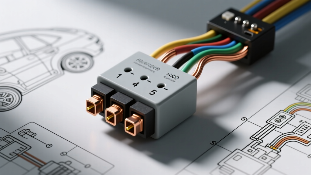
The Engineering Behind a Bad Car Relay
When diagnosing automotive lighting circuit failures, identifying a bad car relay requires more than simply swapping components with a known good unit. It demands a systematic verification of electromagnetic coil integrity, contact resistance, and suppression diode functionality. Modern vehicles utilize ISO 7588-2 standard Mini and Micro relays to control high-current lighting loads, including headlights, fog lamps, and aftermarket light bars. A failing relay can cause intermittent lighting operation, parasitic battery draws, or catastrophic damage to the Body Control Module (BCM) due to inductive voltage spikes.
This technical specification reference outlines the internal construction, precise failure modes, and quantitative diagnostic procedures required to definitively confirm a bad car relay in 12V DC automotive systems.
Internal Anatomy and Failure Modes
To accurately test a relay, a technician must understand the electromechanical forces at play. An ISO Mini relay consists of an electromagnetic coil, a movable armature, and high-current contact points. When diagnosing a bad car relay, failures generally fall into three distinct engineering categories:
1. Electromagnetic Coil Degradation
The coil is a tightly wound spool of copper wire designed to generate a magnetic field when 12V is applied. Over time, thermal cycling and vibration can cause micro-fractures in the copper windings. This results in an 'open coil' condition where resistance becomes infinite. Conversely, insulation breakdown between windings can cause a 'shorted coil,' dropping resistance below operational thresholds and drawing excessive current from the control circuit.
2. Contact Pitting and Carbon Tracking
Lighting circuits, particularly those utilizing halogen bulbs, experience massive inrush currents (often 8 to 10 times the steady-state current) upon initial switch-on. This inrush causes micro-arcing across the relay contacts. Over thousands of cycles, this arcing vaporizes the contact material, creating carbon deposits (tracking) and increasing contact resistance. A bad car relay suffering from carbon tracking will exhibit severe voltage drops, resulting in dim headlights and overheated relay sockets.
3. Suppression Diode Failure
Many modern OEM relays include an internal flyback diode or resistor to suppress the inductive kickback generated when the coil is de-energized. If a technician incorrectly applies reverse polarity to a diode-suppressed relay during testing or installation, the diode will short circuit. This creates a dead short across the control circuit, instantly blowing the BCM driver fuse or destroying the solid-state transistor controlling the relay ground.
ISO 7588-2 Pinout and Specification Matrix
Standard automotive Mini relays utilize a 5-pin configuration (with 4-pin variants omitting the normally closed terminal). The following matrix defines the pin assignments, physical blade widths, and expected baseline specifications for a healthy unit.
| Pin Number | Function | Circuit Type | Blade Width | Expected Baseline Spec |
|---|---|---|---|---|
| 30 | Common (COM) | High-Current Load Input | 6.3 mm (1/4') | Source Voltage (Battery +) |
| 85 | Coil Ground | Low-Current Control | 4.8 mm | Continuity to Chassis Ground |
| 86 | Coil Power | Low-Current Control | 4.8 mm | Switched +12V from BCM/Switch |
| 87 | Normally Open (NO) | High-Current Load Output | 6.3 mm (1/4') | Open Circuit (Unenergized) |
| 87a | Normally Closed (NC) | High-Current Load Output | 6.3 mm (1/4') | Continuity to Pin 30 (Unenergized) |
Quantitative Diagnostic Testing Procedures
Visual inspection of the relay socket for melted plastic or corroded Metri-Pack 280 terminals is the first step. However, confirming a bad car relay requires precise multimeter measurements. Follow these sequential testing parameters to isolate the exact point of failure.
Step 1: Coil Resistance Verification
- Remove the relay from the fuse box and set your Digital Multimeter (DMM) to the Ohms (Ω) setting.
- Place the probes on Pins 85 and 86. A standard 12V automotive relay coil should measure between 60Ω and 120Ω.
- Failure Indicator: If the DMM reads 'OL' (Open Loop), the coil is broken internally. If it reads below 10Ω, the coil has shorted windings. In either case, you have confirmed a bad car relay.
Step 2: Internal Diode / Resistor Check
- Set the DMM to the Diode Test mode (indicated by the diode symbol).
- Place the red probe on Pin 86 and the black probe on Pin 85. A healthy diode-suppressed relay will read a forward voltage drop of approximately 0.5V to 0.7V.
- Reverse the probes (red to 85, black to 86). The meter should read 'OL'. If it reads near 0.0V in both directions, the suppression diode has failed shorted.
Step 3: Contact Resistance and Voltage Drop
Testing continuity with an ohmmeter is insufficient because the DMM applies less than 1mA of current. A bad car relay with carbon-pitted contacts may show continuity under 1mA but fail completely under a 15A headlight load.
- Use a dedicated 12V relay tester or apply 12V directly to Pins 85 and 86 using fused jumper wires. You should hear an audible, sharp 'click'.
- With the coil energized, measure the resistance between Pin 30 and Pin 87. The specification is strictly < 50 milli-ohms (0.050Ω).
- Load Testing: For absolute certainty, wire the relay in series with a 10A dummy load (such as a 55W halogen bulb) and a 12V power supply. Measure the DC Voltage Drop across Pins 30 and 87 while the circuit is active. A voltage drop exceeding 0.1V (100mV) indicates severe internal pitting, necessitating immediate replacement.
Inrush Current and Contact Welding Failures
One of the most common causes of a bad car relay in modified lighting systems is contact welding. When enthusiasts upgrade from 55W halogen bulbs to high-draw off-road LED light bars or HID ballasts without utilizing a soft-start PWM module, the initial capacitive inrush current can exceed 40A for several milliseconds. Standard 30A ISO Mini relays are rated for 30A continuous, but their make/break capacity is often insufficient for massive inductive or capacitive spikes.
This extreme current causes the contacts to physically melt and fuse together. When the BCM removes the ground from Pin 85, the magnetic field collapses, but the armature remains physically stuck to the welded contacts. The result is a lighting circuit that remains permanently energized, leading to a dead battery or a melted wiring harness. For high-inrush aftermarket lighting, technicians must specify Bosch-style heavy-duty 40A or 50A relays with silver-tin oxide (AgSnO2) contact materials, which are highly resistant to welding and arc erosion.
Wiring Harness and Terminal Specifications
When replacing a bad car relay and repairing the associated pigtail or harness, adhering to strict wire gauge and crimping specifications is mandatory to prevent future thermal failures.
- Load Circuit (Pins 30, 87, 87a): For 30A relays, use a minimum of 14 AWG cross-linked polyethylene (GXL or TXL) wire. For 40A relays, step up to 12 AWG.
- Control Circuit (Pins 85, 86): 18 AWG GXL wire is sufficient for the low-current coil circuit.
- Terminals: Use tin-plated copper female spade terminals (6.3mm for load, 4.8mm for coil). Never use bare brass or nickel-plated terminals in under-hood environments, as they oxidize rapidly and increase contact resistance.
- Sealing: All connections must utilize silicone cavity plugs and wire seals (e.g., Delphi Weather-Pack or TE Metri-Pack 280 series) to prevent capillary action from drawing moisture into the relay socket.
Authoritative References
For further engineering data on automotive relay specifications and lighting circuit testing, refer to the following industry standards and manufacturer application guides:
- Littelfuse Automotive Relay Specifications and Application Guides - Comprehensive data on contact materials, coil resistance tolerances, and inrush current handling for ISO Mini relays.
- Omron Automotive Relay Technical Datasheets - Detailed schematics on internal suppression diodes, resistor networks, and thermal derating curves.
- SAE J575: Tests for Motor Vehicle Lighting Devices and Components - Society of Automotive Engineers standards for environmental and electrical testing of automotive lighting components and associated switching relays.
Summary
Accurately diagnosing a bad car relay requires moving beyond simple continuity checks. By utilizing quantitative resistance measurements, performing loaded voltage drop tests, and understanding the material science of contact degradation, automotive electrical technicians can definitively isolate relay failures. Always ensure replacement relays match the OEM coil resistance and suppression diode orientation to protect sensitive BCM circuitry, and verify that wire gauges are appropriately sized for the specific thermal demands of the lighting load.