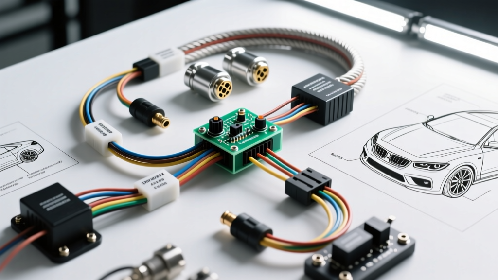
Advanced Rock Lights Wiring Diagram & Architecture
Most commercial rock light kits fail prematurely because they rely on undersized 18 AWG wiring, cheap inline toggle switches, and lack proper isolation from the vehicle's sensitive multiplexed electrical networks. When installing high-output LED rock lights on modern off-road vehicles like the Jeep Wrangler JK (2007-2018) or JL (2018-present), tapping directly into the factory fuse panel can trigger catastrophic failures in the Totally Integrated Power Module (TIPM) or Body Control Module (BCM). An advanced, expedition-grade installation requires a dedicated power distribution architecture, a 4-pin ISO mini relay, and a high-frequency Pulse Width Modulation (PWM) controller to eliminate camera flicker and ensure thermal stability.
The TIPM/BCM Isolation Requirement
In Jeep Wrangler JK models, the TIPM handles logic switching and power distribution. Drawing more than a few amps directly from a TIPM-fused accessory circuit to power a 6-pod or 8-pod rock light array (which can pull 6A to 12A depending on the LED drivers) can overheat the internal PCB traces, leading to a $1,200+ TIPM replacement. The correct methodology is to use the factory circuit solely as a low-current trigger signal (under 1A) to switch a heavy-duty relay, pulling the main current directly from the battery via a dedicated fused line. For JL models and newer CAN bus systems, utilizing a CAN bus decoder or an isolated relay prevents the BCM from detecting an 'out of range' current draw, which would otherwise trigger a hyper-flash or a CEL (Check Engine Light) for a lighting circuit fault.
Comprehensive Rock Lights Wiring Diagram Breakdown
The following schematic outlines an 8-pod rock light configuration utilizing a Bosch-style 4-pin relay, an inline PWM dimmer, and DEUTSCH DT series waterproof connectors. This setup conforms to the SAE J1128 Low Tension Primary Cable Standard for automotive wire sizing and insulation.
Primary Power & Relay Circuit
- Battery Positive (+) to ATO Fuse Block: 10 AWG Red SAE J1128 wire. Terminate with a 3/8" ring terminal and marine-grade adhesive heat shrink. Mount a 30A MAXI or 20A ATO fuse within 18 inches of the battery terminal.
- Fuse Block to Relay Pin 30 (Common): 10 AWG Red wire.
- Relay Pin 87 (Normally Open) to PWM Controller Power In: 12 AWG Red wire.
- Relay Pin 85 (Coil Ground) to Chassis Ground: 14 AWG Black wire, secured to a factory ground bolt with a star washer to bite through the paint.
- Ignition Switched 12V (Add-A-Circuit) to Relay Pin 86 (Coil Power): 16 AWG Blue wire. Tap into a low-amperage ignition-switched fuse (e.g., 12V power outlet or radio fuse) using an Add-A-Circuit pigtail to prevent backfeeding.
Secondary Load & PWM Circuit
- PWM Controller Ground to Chassis Ground: 12 AWG Black wire.
- PWM Controller Output (+) to DEUTSCH DT 4-Way Splitter Hub: 12 AWG Red wire.
- DEUTSCH Hub Branches to LED Pod Pigtails: 16 AWG Red/Black split loom, terminating in IP68 waterproof screw-lock connectors at each wheel well.
Pinout & Wire Routing Matrix
| Circuit Segment | Wire Gauge (AWG) | Color Code | Connector / Termination | Protection / Routing |
|---|---|---|---|---|
| Battery to Fuse | 10 AWG | Red | 3/8" Ring Terminal | Split Loom, away from exhaust |
| Fuse to Relay Pin 30 | 10 AWG | Red | 1/4" Female Spade | Tesa Cloth Tape |
| Relay Pin 87 to PWM In | 12 AWG | Red | 1/4" Female Spade | Engine Bay Harness Wrap |
| Relay Pin 85 to Ground | 14 AWG | Black | 1/4" Ring Terminal | Zip-tie to chassis |
| Add-A-Circuit to Pin 86 | 16 AWG | Blue | Posi-Tap / Add-A-Circuit | Interior Cabin Routing |
| PWM Out to DEUTSCH Hub | 12 AWG | Red/Black | DEUTSCH DT04-4P-E004 | Underbody Skid Plate Routing |
| Hub to LED Pods (x8) | 16 AWG | Red/Black | IP68 Screw-Lock | Flex Loom, away from tie-rods |
Voltage Drop Calculations for Parallel LED Pods
A common failure mode in rock light installations is rear pods appearing dimmer than front pods due to excessive voltage drop in undersized branch wiring. According to Littelfuse Automotive Relay Specifications, maintaining optimal voltage at the load ensures the internal constant-current LED drivers operate efficiently without thermal throttling.
Assume an 8-pod setup drawing 0.75A per pod (6A total). The longest branch run from the central DEUTSCH hub to the rear wheel well is approximately 12 feet (24 feet total circuit length including ground).
Voltage Drop Formula: VD = (2 x L x I x R) / 1000
Where L = 12ft, I = 3A (per branch feeding 4 pods), R = 4.016 ohms/1000ft for 16 AWG copper.
VD = (2 x 12 x 3 x 4.016) / 1000 = 0.289 Volts.
A 0.29V drop on a 12.6V system is well within the acceptable 3% threshold (0.378V). However, if 18 AWG wire (R = 6.385) were used, the drop would be 0.459V, pushing the rear pods below the optimal voltage threshold and causing noticeable dimming or flickering under heavy alternator ripple. Always use a minimum of 16 AWG for branch runs and 12 AWG for the main trunk.
PWM Frequency & Action Camera Flicker
Standard cheap dimmers use low-frequency PWM (typically 60Hz to 100Hz). While this works for the human eye, it causes severe rolling band interference when recording with action cameras (GoPro, DJI) or smartphone sensors, which operate at high shutter speeds. To eliminate camera flicker, your PWM controller must operate at a minimum frequency of 1kHz to 2kHz. High-frequency PWM ensures the LED duty cycle switches faster than the camera's rolling shutter readout, resulting in solid, flicker-free illumination on trail cameras and POV vlogs.
IP68 Termination & Waterproofing Standards
Rock lights are subjected to hydrostatic pressure from water crossings, abrasive mud, and road salt. Standard crimp connectors will corrode within months. Follow the TE Connectivity DEUTSCH DT Series Datasheet guidelines for underbody harness construction:
- Crimp & Solder: Use an open-barrel crimp tool for DEUTSCH solid pins, followed by a light solder wick to prevent capillary action from drawing moisture into the wire strands.
- Silicone Wedges: Never omit the secondary silicone wedge seal inside the DEUTSCH connector. It provides the secondary IP68 hydrostatic barrier.
- Adhesive Heat Shrink: For any inline splices, use 3M ITCSN or equivalent dual-wall polyolefin heat shrink with an internal thermoplastic adhesive lining. When heated, the adhesive melts and extrudes from the ends, creating a watertight seal that blocks capillary moisture migration.
- Drip Loops: Always route the final pigtail into the LED pod with a 'drip loop' (a U-shape below the connector) so that water running down the harness drips off the bottom of the loop rather than pooling inside the connector housing.
Advanced Troubleshooting Decision Tree
- Symptom: Lights flicker at idle but stabilize at highway RPMs.
Cause: Alternator AC ripple exceeding the PWM controller's filtering capacitors, or a loose chassis ground.
Fix: Clean chassis ground to bare metal; install a 10,000µF filter capacitor in parallel with the PWM power input. - Symptom: Relay clicks rapidly (chatter) but lights do not illuminate.
Cause: Voltage drop on the trigger wire (Pin 86) causing the relay coil to rapidly engage and disengage.
Fix: Upgrade the trigger wire from 18 AWG to 14 AWG, or move the Add-A-Circuit tap to a higher-amperage ignition source. - Symptom: CAN Bus throws a 'Lighting Circuit Open' CEL on a JL Wrangler.
Cause: The BCM expects a specific resistive load on the auxiliary lighting circuit, and the high-efficiency LED draw is too low.
Fix: Wire a 10-ohm, 50W ceramic power resistor in parallel with the trigger circuit to simulate an incandescent halogen load, or use a dedicated CAN bus bypass module.
Thermal Management & Wire Loom Routing
When routing the main 10 AWG and 12 AWG harness through the firewall and underbody, maintain a minimum 6-inch clearance from the exhaust manifold and catalytic converter. Use Tesa 51036 PET cloth tape for engine bay harness wrapping to resist abrasion and high heat. Under the chassis, transition to corrugated split loom secured with UV-resistant zip-ties and aluminum P-clamps bolted to existing frame holes. Avoid drilling new holes in the frame rails, as this compromises the structural integrity and introduces new rust nucleation points.