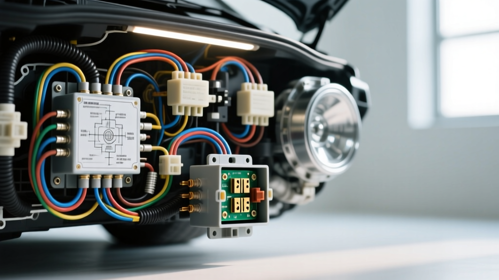
Understanding the 'Car Relay Fuse' Architecture
In automotive electrical diagnostics, the term car relay fuse is technically a conflation of two distinct but symbiotic components: the electromechanical relay (the switch) and the fuse (the overcurrent protector). When dealing with aftermarket lighting installations—such as H4 headlight relay harnesses, LED light bar wiring, or fog light kits—these two components are often integrated into a single weatherpack harness or housed adjacently within the vehicle's Power Distribution Center (PDC).
A relay isolates the high-amperage lighting load from the low-amperage factory dashboard switch. The fuse protects the high-amperage feed wire (typically feeding Pin 30) from melting in the event of a short to ground. When a lighting circuit fails, blindly replacing the fuse without executing a structured diagnostic flow will result in repeated failures and potential wire harness fires. This guide provides a step-by-step troubleshooting flow to isolate faults in fused relay lighting circuits, utilizing standard ISO mini-relay pinouts and SAE wiring specifications.
Phase 1: Component Isolation & Baseline Testing
Before tracing wires through the engine bay, you must verify the baseline health of the relay and the fuse. You will need a digital multimeter (DMM) set to Ohms (Ω) for resistance testing and DC Volts (V) for live circuit testing.
1. Testing the Inline ATO/Mini Fuse
Do not rely on visual inspection alone. A hairline fracture in the fusible link can appear intact but fail under load. Pull the fuse and set your DMM to the continuity or resistance setting. Place a probe on each blade of the fuse.
- 0.0Ω to 0.5Ω: Fuse is intact.
- OL (Open Loop) or Infinite Resistance: Fuse is blown. Do not replace yet. A blown fuse indicates a downstream short to ground or a severe overcurrent event on Pin 87 (the load wire).
2. Testing the ISO Mini Relay Coil
Standard automotive lighting uses the ISO 7588-1 mini relay. The electromagnetic coil is located between Pin 85 and Pin 86.
- Set the DMM to Ohms (Ω).
- Probe Pin 85 and Pin 86.
- Expected Reading: 65Ω to 90Ω for a standard 12V relay coil.
- Failure Mode: If the reading is OL, the internal coil wire is broken. If the reading is near 0Ω, the coil is internally shorted. In either case, replace the relay.
- Note on Diode-Protected Relays: If your relay has an internal suppression diode (common in German vehicles and high-end light bar harnesses), it is polarity-sensitive. If you get an OL reading, swap your red and black DMM probes and test again.
Phase 2: Step-by-Step Diagnostic Decision Tree
Use this logical flow to pinpoint the exact failure node in your lighting circuit. Start at Node A.
Node A: Activate the Lighting Switch. Does the relay emit an audible 'click'?
Path 1: YES, the relay clicks, but the lights do not turn on.
- Check the Fuse: Pull the car relay fuse. Is it blown?
- If Blown: You have a direct short to ground on the Pin 87 load wire (the wire running from the relay to the lights). Inspect the wire for chafing against the chassis, melted insulation near exhaust manifolds, or water intrusion in the light housing causing a dead short. Repair the wire, upgrade to cross-linked TXL wire, and replace the fuse.
- If Intact: Power is not reaching the lights. Move to Step 2.
- Test Pin 30 (Power In): Set DMM to DC Volts. Probe the harness side of Pin 30 with the black lead on a known good chassis ground. You should read 12.2V - 12.6V. If 0V, the battery feed wire is severed or the main battery fusible link is blown.
- Test Pin 87 (Power Out): With the relay plugged in and the switch activated, back-probe the Pin 87 wire. If you read 12V here but the lights are off, the fault is a broken ground wire at the headlight bucket or a blown bulb.
Path 2: NO, the relay does not click.
- Check the Trigger Circuit: The relay coil requires a 12V trigger (usually Pin 86) and a ground (usually Pin 85). Back-probe Pin 86 with the switch activated.
- If 12V is present: The issue is on the ground side. Check Pin 85 for continuity to the chassis. Many aftermarket harnesses use a ring terminal for Pin 85; ensure it is not bolted to painted metal or a rusted strut tower.
- If 0V is present: The trigger signal is failing to reach the relay. If your harness utilizes a secondary low-amp fuse for the trigger wire (often a 5A Mini fuse tapping into the factory headlight circuit), check this secondary fuse.
Technical Matrix: Lighting Relay Harness Specifications
When building, repairing, or upgrading a fused relay harness for high-draw lighting (e.g., 100W off-road halogens or 50-inch LED light bars), adhering to the correct AWG (American Wire Gauge) and pinout matrix is critical to prevent voltage drop and thermal events.
| Relay Pin | Function | Standard Wire Color | Recommended AWG (TXL/GXL) | Max Continuous Amperage | Fuse Protection Requirement |
|---|---|---|---|---|---|
| 30 | 12V Battery Feed (Common) | Red | 10 AWG to 12 AWG | 30A - 40A | Main Inline ATO/ATC Fuse (Sized to wire gauge, e.g., 30A for 10AWG) |
| 87 | Load Output (To Lights) | Yellow / White | 12 AWG to 14 AWG | 20A - 30A | Protected by Pin 30 Fuse (or secondary inline if split to dual lamps) |
| 86 | Trigger (From Dash Switch) | Blue / Black | 16 AWG to 18 AWG | 2A - 5A | Tapped into factory circuit (protected by OEM fuse) or inline 5A Mini |
| 85 | Coil Ground | Black | 16 AWG to 18 AWG | 2A - 5A | None (Requires clean chassis ground) |
Phase 3: Resolving Chronic 'Car Relay Fuse' Failures
If your diagnostic flow reveals that the fuse is intact, the wiring is undamaged, but the car relay fuse continues to blow intermittently or immediately upon startup, you are likely dealing with one of the following advanced electrical anomalies.
1. Cold Filament Inrush Current (Halogen & HID Systems)
Standard automotive fuses are rated for continuous current, but lighting circuits suffer from massive inrush spikes. A standard 55W H4 halogen bulb draws roughly 4.5 Amps at operating temperature. However, the cold resistance of a tungsten filament is approximately 1/10th of its hot resistance. Upon initial startup, a single H4 bulb can pull 15 to 20 Amps for 200 milliseconds. If you are running a dual-headlight relay harness with 100W bulbs on a single 15A ATO fuse, the inrush spike will fatigue and eventually blow the fuse element, even if the steady-state draw is within limits. Fix: Upgrade to a 25A or 30A ATO fuse and ensure the Pin 30 feed wire is upgraded to 10 AWG TXL to handle the thermal load safely.
2. LED Upgrades and CANBUS Voltage Spikes
When replacing factory halogen fog lights with LED pods using a relay harness, the vehicle's Body Control Module (BCM) may misinterpret the low current draw of the LED as a 'blown bulb' error. The BCM will rapidly pulse the trigger circuit (PWM signaling) to check the bulb, causing the relay to chatter violently. This rapid make/break cycle of the relay contacts creates inductive voltage spikes (back-EMF) that can arc across the relay contacts and blow the inline fuse. Fix: Install a CANBUS error-canceling capacitor module in parallel with the trigger circuit, or use a solid-state relay (SSR) which is immune to contact arcing and PWM chatter.
3. Voltage Drop and Thermal Fuse Fatigue
Fuses blow due to heat. If your fuse holder is located near the radiator or exhaust headers, ambient heat lowers the current threshold required to melt the fusible link. Furthermore, if you are using cheap, stamped-brass fuse taps instead of oxygen-free copper (OFC) wiring, resistance at the fuse holder generates localized heat. According to Littelfuse automotive engineering guidelines, a standard ATO fuse carrying 80% of its rated continuous load in an ambient temperature of 85°C (185°F) will experience premature thermal fatigue and open the circuit. Fix: Relocate the inline fuse holder away from engine heat sources and use high-temperature ATC/ATO fuse holders with silicone seals.
Authoritative References & Standards
- SAE J1284 / ISO 8820-3: Standard specifications for blade-type automotive fuses (ATO/ATC/Mini), defining time-current characteristics and temperature derating curves. Reference: SAE International.
- ISO 7588-1: Road vehicles — Relays — Part 1: Definitions and general requirements for 12V/24V automotive electromechanical relays. Defines the standard 4-pin and 5-pin mini-relay footprint and coil resistance tolerances.
- Automotive Electrical Systems Fundamentals: Comprehensive relay circuit logic and voltage drop testing methodologies. Reference: AutoShop101 - Relays and Solid State Switches.