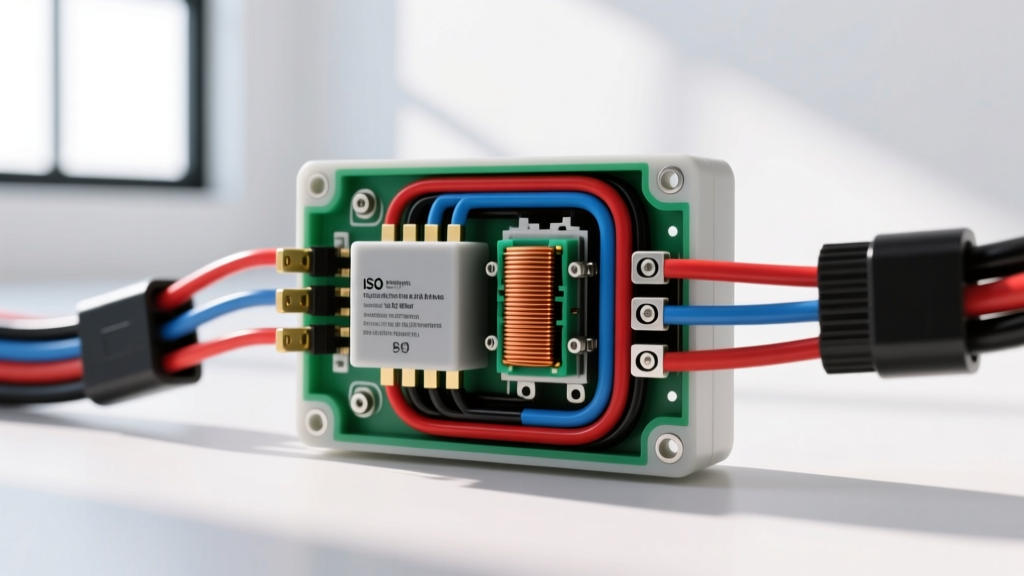
The Hidden Dangers of Misidentifying Car Relay Types
When upgrading automotive lighting systems, installing auxiliary fog lights, or rewiring aging headlight circuits, the electromagnetic relay is your most critical component. A relay isolates high-current loads from delicate factory switches and ECU driver circuits. However, a fundamental misunderstanding of car relay types and their internal architectures leads to catastrophic electrical failures, melted wiring harnesses, and fried control modules. According to the SAE J553 standard for automotive relays, these components must withstand severe thermal and vibrational stress, but improper wiring negates these engineering safeguards. This guide dissects the most dangerous wiring mistakes associated with ISO, Micro, and Solid-State relays, providing actionable safety warnings for 12V DC automotive applications.
ISO Mini vs. Micro Relays: The Physical Fitment Trap
The most common mistake in aftermarket lighting installations is forcing a relay into an incompatible socket or misidentifying the footprint. The ISO 7588-1 standard dictates the physical dimensions of automotive relays, but variations exist that can cause immediate dead shorts.
- ISO Mini Relays (Standard): Feature 6.3mm wide blade terminals. These are the industry standard for 30A to 40A circuits, such as halogen light bars and radiator fan upgrades. The standard footprint is roughly 25.4mm x 25.4mm.
- ISO Micro Relays: Feature 2.8mm narrow blade terminals. Designed for low-current applications (15A to 20A) like fuel pumps, horn circuits, or LED pod lights. The footprint is significantly smaller (roughly 15mm x 20mm).
The Mistake: Attempting to adapt a Micro relay into a Mini socket using jumper wires or bending the 2.8mm pins to fit 6.3mm female spade connectors. This creates massive surface-area contact resistance. Under a continuous 15A load, this poor connection will generate enough heat to melt the ABS plastic relay socket and potentially ignite the wire insulation.
The Fix: Always match the relay footprint to the OEM socket. If adapting a circuit, use a dedicated pigtail harness with the correct sealed AMP/Tyco connectors rather than modifying the relay pins.
Bosch (European) vs. Japanese Pinout Standards
Terminal numbering follows the DIN 72552 standard, but the physical layout of the pins on the bottom of the relay varies drastically between European (Bosch-style) and Japanese manufacturers (common in Honda, Toyota, and Subaru vehicles). Assuming the pinout based on the plastic molding diagram alone is a frequent cause of short circuits.
| Terminal | DIN 72552 Function | Bosch ISO Mini Layout | Japanese 4-Pin Layout |
|---|---|---|---|
| 30 | Common (Battery Power In) | Bottom Left | Bottom Left |
| 87 | Normally Open (Load Out) | Top Left | Top Right |
| 85 | Coil Ground | Bottom Right | Top Left |
| 86 | Coil Power (Trigger) | Top Right | Bottom Right |
The Mistake: Wiring a Japanese-style relay using a Bosch wiring diagram. Because pins 85 and 87 are swapped on the physical grid, applying 12V battery power to what you believe is Terminal 30 might actually send 12V directly into the ECU trigger circuit (Terminal 85/86), instantly destroying the vehicle's body control module (BCM) or headlight switch.
The Fix: Always use a digital multimeter (DMM) in continuity mode to verify the coil pins (which will read 60 to 120 ohms) and the switched pins (which will read infinite resistance/open circuit when de-energized) before applying power. Consult the Hella Technical Relay Guide for OEM-specific footprint diagrams.
The 5-Pin Changeover Disaster: Misusing Terminal 87a
A 5-pin relay adds Terminal 87a (Normally Closed). In a de-energized state, power flows from 30 to 87a. When the coil is energized, the internal armature pulls away from 87a and connects 30 to 87. These are frequently used for DRL (Daytime Running Light) logic or alarm starter-kill circuits.
The Mistake: Wiring both 87 and 87a to the same load to 'ensure' power delivery, or using a 5-pin relay in a standard 4-pin application without insulating the unused 87a terminal. If moisture enters the relay socket, or if the internal contacts bounce during high-vibration off-road driving, the load can receive power from both circuits simultaneously, bypassing fuses or creating a feedback loop into the alternator.
Safety Warning: Never use a 5-pin relay as a substitute for a 4-pin relay in high-current lighting applications (like 55W H1 halogen fog lights) unless the 87a terminal is physically clipped off or completely sealed with dielectric grease and a dummy cap. The internal armature of a 5-pin relay is slightly heavier, making it more susceptible to contact bounce under severe G-forces.
Inductive Kickback: The Flyback Diode Mandate
When the trigger circuit (pins 85/86) is turned off, the magnetic field in the relay coil collapses. This generates a massive reverse-voltage spike (back-EMF), often exceeding 100V for a fraction of a millisecond. If this relay is triggered directly by a solid-state ECU driver or a delicate aftermarket LED controller, this spike will punch through the silicon junction, destroying the transistor.
The Mistake: Installing a standard relay without an internal flyback diode (or suppression resistor) on an ECU-controlled circuit. Conversely, installing a relay with an internal diode backward (reverse polarity on pins 85 and 86). If a diode-equipped relay is wired with reverse polarity, the diode will act as a dead short across the 12V trigger source the moment the switch is closed, instantly blowing the control fuse or melting the trigger wire.
The Fix: If triggering a relay via an ECU pin or a sensitive PWM dimmer module, you must use a relay with an internal flyback diode. Always check the schematic printed on the relay casing to verify diode polarity. As detailed in the Littelfuse Automotive Relay Guide, the cathode stripe on the internal diode must face the positive trigger source (Terminal 86).
Trigger Circuit Failures: Wire Gauge and Voltage Drop
While the high-current load circuit (pins 30 and 87) requires heavy-gauge wire (typically 10 AWG or 12 AWG for 30A-40A loads), the trigger circuit (pins 85 and 86) is often neglected.
The Mistake: Using 22 AWG wire for a relay coil trigger that runs 15 feet from the dashboard switch to the engine bay. A standard 12V automotive relay coil requires roughly 150mA to 200mA to pull in. While 22 AWG can handle this current, the resistance over a 30-foot round trip (power and ground) causes a severe voltage drop. If the voltage at the coil drops below 9V, the relay will chatter, arc internally, and weld the contacts together, leaving your light bar on permanently even when the truck is turned off.
The Fix: Use a minimum of 16 AWG GXL wire for all relay trigger circuits, regardless of the low amperage. This minimizes voltage drop and provides mechanical durability against engine bay vibrations. Always fuse the trigger wire at the source with a 5A or 10A ATM/ATC fuse.
Solid-State Relays (SSRs) vs. Electromechanical
Modern lighting upgrades often tempt installers to use Solid-State Relays (SSRs) due to their silent operation, lack of moving parts, and infinite lifecycle. However, SSRs behave entirely differently than electromagnetic car relay types.
The Mistake: Using an SSR rated for 40A continuous current to drive a massive LED light bar. While LEDs draw low continuous current, they utilize massive capacitor banks that cause extreme inrush current (sometimes 10x the continuous draw) for the first few milliseconds. An SSR lacking specific inrush-current tolerance will suffer thermal runaway and fail in the 'closed' (ON) position, creating a severe fire hazard.
The Fix: For high-inrush LED arrays or halogen bulbs, stick to high-quality electromechanical ISO Mini relays with silver-nickel alloy contacts. If you must use an SSR for PWM dimming or CAN-bus integration, ensure the SSR is specifically rated for 'high inrush' or 'capacitive loads', and mount it to a heatsink, as SSRs generate significant waste heat at high amperages.
Safety Warnings & Best Practices Checklist
To ensure a safe, reliable, and fire-proof lighting installation, adhere to these non-negotiable electrical standards:
- Relay Socket Quality: Avoid cheap, stamped-brass aftermarket sockets. Use OEM-style sockets with beryllium-copper or phosphor-bronze terminals that maintain high clamping force. Loose terminals cause high resistance, leading to melted housings.
- Proximity to Battery: Mount the relay as close to the battery as possible. The heavy 10 AWG wire from the battery to Pin 30 should be as short as feasible to minimize the length of unfused (or newly fused) high-current wire in the engine bay.
- Main Power Fusing: ALWAYS place a Mega or ANL fuse within 18 inches of the battery positive terminal on the wire feeding Pin 30. The relay itself is not a protective device; it is a switch.
- Environmental Sealing: If mounting relays in the wheel well, grille, or undercarriage, use IP67-rated sealed relays and pot the socket connections with marine-grade heat shrink tubing containing adhesive lining to prevent capillary action wicking of water into the harness.
- Crimping Standards: Never solder relay spade connectors. Solder wicks up into the wire strand, creating a brittle stress point that will snap under engine vibration. Use a ratcheting open-barrel or closed-barrel crimper with the correct gauge die, followed by dual-wall adhesive heat shrink.