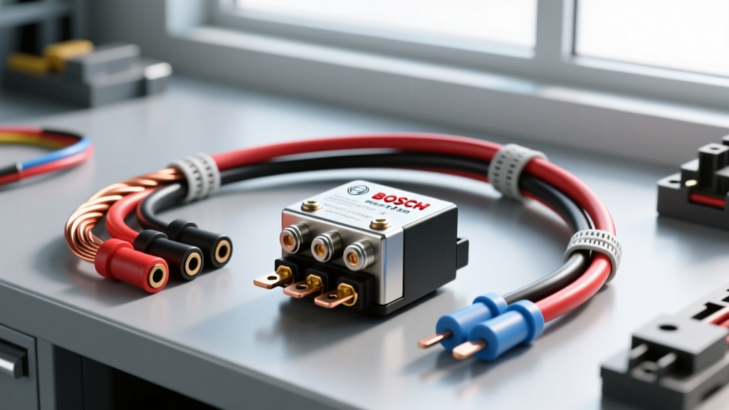
Introduction to Electromechanical Switching in Automotive Lighting
When executing high-draw automotive lighting upgrades—such as installing 100W H4 halogen bulbs, HID conversion ballasts, or multi-row LED light bars—the factory headlight switch and OEM wiring harness are rarely sufficient. Factory circuits are typically designed with minimal overhead, utilizing 18 or 20 AWG wire and low-amperage switches that suffer from severe voltage drop under increased loads. To bypass these limitations, technicians must implement a dedicated, high-current circuit governed by an electromechanical switch. Understanding the architecture of a robust 12 volt relay wiring diagram is the foundational skill required to isolate the high-current load path from the low-current trigger circuit, ensuring optimal lumen output and preventing catastrophic harness fires.
Deconstructing the Standard 12 Volt Relay Wiring Diagram
The industry standard for automotive lighting relays is the micro ISO relay, often referred to generically as a 'Bosch-style' relay. These relays operate on a 12V DC electromagnetic coil that actuates a movable armature to bridge high-current contacts. The terminal designations follow the DIN 72552 standard, which ensures universal compatibility across OEM and aftermarket wiring harnesses.
DIN 72552 Terminal Designations and Pinout Architecture
A standard 5-pin micro ISO relay utilizes five 6.3mm (1/4 inch) male spade terminals. While 4-pin variants omit the normally closed circuit, the 5-pin configuration offers maximum versatility for complex lighting logic, such as fog light interlocks or daylight running light (DRL) overrides.
| Terminal ID | Function | Recommended AWG | SAE J1128 Color Code | Connector Specification |
|---|---|---|---|---|
| 30 | Common (Battery Power In) | 10 or 12 AWG | Red | Aptiv Metri-Pack 280 |
| 85 | Coil Ground | 16 or 18 AWG | Black | Aptiv Metri-Pack 150 |
| 86 | Coil Power (Trigger Switch) | 16 or 18 AWG | White or Yellow | Aptiv Metri-Pack 150 |
| 87 | Normally Open (Load Out) | 10 or 12 AWG | Blue or Green | Aptiv Metri-Pack 280 |
| 87a | Normally Closed (Auxiliary) | 12 or 14 AWG | Orange | Aptiv Metri-Pack 150 |
High-Current Headlight Upgrade: Step-by-Step Wiring Architecture
Designing a reliable 12 volt relay wiring diagram requires more than simply connecting wires to the correct pins; it demands strict adherence to voltage drop thresholds and environmental sealing standards.
Calculating Voltage Drop and AWG Requirements
Automotive lighting systems require a minimum of 13.2V at the bulb socket to achieve rated lumen output and optimal color temperature. According to SAE J1128 standards, standard primary wire (GPT) has higher resistance and lower thermal tolerance than cross-linked polyethylene (XLPE) insulated wires like GXL or TXL. For a 12 AWG GXL wire, the resistance is approximately 1.588 milliohms per foot at 20°C.
If you are routing a 15A headlight circuit with a 20-foot round-trip distance (10 feet to the relay, 10 feet to the ground), the voltage drop is calculated as: V_drop = Current x Resistance. Therefore, 15A x (20 ft x 0.001588 ohms/ft) = 0.476V. This leaves 13.72V at the load (assuming a 14.2V alternator output), which is well within acceptable parameters. However, if 16 AWG wire were mistakenly used for the load circuit, the voltage drop would exceed 1.2V, leading to dim lighting and excessive heat generation in the harness.
Termination and Environmental Sealing Standards
Wire terminations must comply with IPC-A-620 automotive cable assembly standards. Open-barrel crimps (F-crimps) are preferred for high-vibration environments due to their superior tensile strength and lower electrical resistance compared to closed-barrel crimps. Always utilize a ratcheting crimp tool calibrated for the specific AWG and terminal type. Furthermore, all splices and ring terminals exposed to the engine bay must be sealed using dual-wall, adhesive-lined heat shrink tubing. The inner thermoplastic adhesive melts and flows into the wire strands, preventing capillary action and copper oxidation—a common failure point in poorly executed relay diagrams.
Advanced Diagnostics: Relay Coil Flyback and Contact Bounce
When integrating a 12 volt relay wiring diagram into modern vehicle architectures, technicians must account for inductive kickback and solid-state switching sensitivities.
Integrating Flyback Diodes and TVS Suppressors
A relay coil is fundamentally an inductor. When the trigger circuit (Pin 86) is opened, the collapsing magnetic field induces a high-voltage reverse polarity spike (Back-EMF) that can exceed 100V. If the relay is triggered by a solid-state switch, a Body Control Module (BCM), or an LED headlight driver, this spike will instantly destroy the semiconductor junction. To mitigate this, a flyback diode (such as a 1N4001 or 1N4004) must be wired in parallel across Pins 85 and 86. The diode must be oriented with the cathode (stripe) facing Pin 86 (positive trigger) and the anode facing Pin 85 (ground). This creates a localized recirculation loop that safely dissipates the inductive energy as heat.
Thermal Management and Contact Welding Failure Modes
A frequent failure mode in aftermarket lighting diagrams is contact welding. HID ballasts and large LED drivers draw massive inrush currents upon startup—often 3 to 5 times their steady-state operating current. If a standard 30A micro ISO relay is subjected to a 90A inrush spike, the microscopic arcing across the contacts as they close can cause the silver-tin oxide alloy to melt and fuse together. This results in the lights remaining permanently illuminated. For high-inrush applications, the 12 volt relay wiring diagram must specify either a heavy-duty 80A continuous-duty solenoid or a solid-state relay (SSR) with zero-crossing detection.
Modern Vehicle CAN-Bus and PWM Integration
In vehicles manufactured after 2015, factory headlight circuits rarely provide a steady 12V DC trigger signal. Instead, manufacturers utilize Pulse Width Modulation (PWM) to control bulb intensity or monitor circuit health via CAN-bus. If you connect Pin 86 of a standard relay directly to a PWM headlight wire, the relay will chatter violently at frequencies between 50Hz and 500Hz, rapidly destroying the contacts and failing to illuminate the lights.
To correctly adapt a 12 volt relay wiring diagram for a PWM-triggered vehicle, you must install a PWM-to-DC signal conditioner or a CAN-bus isolation module between the factory harness and Pin 86. These modules read the PWM duty cycle, verify the signal is a valid 'ON' command, and output a clean, steady 12V DC signal to actuate the relay coil without triggering a BCM open-circuit fault code.
Structured Troubleshooting Decision Tree
When a newly installed relay circuit fails, utilize this systematic diagnostic sequence before replacing components:
- Symptom: Relay clicks audibly, but lights do not illuminate.
- Step 1: Measure voltage at Pin 30. If < 12V, check the main inline fuse and battery ring terminal crimp.
- Step 2: Measure voltage at Pin 87 with the relay energized. If 0V, the internal armature is faulty or Pin 30/87 contacts are carbon-fouled.
- Step 3: If Pin 87 shows 12V, the fault lies downstream. Check the load ground termination for paint, rust, or loose ring terminals.
- Symptom: Relay does not click when the switch is activated.
- Step 1: Measure coil resistance across Pins 85 and 86. A healthy 12V micro ISO coil should read between 60 and 90 ohms. An infinite reading indicates a broken internal copper winding.
- Step 2: Backprobe Pin 86 during activation. If voltage is absent, trace the trigger wire back to the cabin switch or PWM decoder.
- Step 3: Verify the ground at Pin 85 using a voltage drop test under load. A ground circuit dropping more than 0.1V will starve the coil of the necessary amperage to pull the armature.
By adhering to these advanced electrical principles, proper AWG sizing, and environmental sealing protocols, your 12 volt relay wiring diagram will provide a lifetime of reliable, high-output lighting performance. For further reading on automotive electromagnetic compatibility and relay suppression, refer to the Littelfuse Automotive Relay Application Guide and the Aptiv Connection Systems Engineering Specifications.