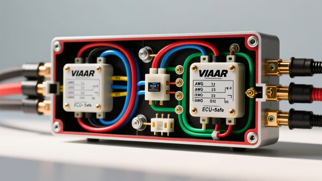
Why Factory Air Ride Relays Fail in Dual Compressor Upgrades
Upgrading to a dual compressor setup—such as twin VIAIR 400C units for an Air Lift Performance 3P or 3H air management system—drastically increases the electrical load on your vehicle. The standard air ride relay wiring diagram provided in basic single-compressor kits typically relies on a standard 30A or 40A Bosch-style cube relay. When subjected to the combined 30-40A continuous draw and 60A+ startup surge of dual compressors, these standard spade terminals overheat, melt the relay housing, and cause catastrophic voltage drops.
Furthermore, modern digital air ride ECUs are highly sensitive to inductive kickback. When a high-amp relay coil de-energizes, it sends a voltage spike back through the trigger wire. Without proper flyback diode integration, this spike will fry the internal pressure switch transistors on your Air Lift Performance manifold. This guide provides a comprehensive, ECU-safe air ride relay wiring diagram tailored for heavy-duty dual compressor upgrades.
Required Components & Wire Gauge Specifications
To ensure SAE compliance and prevent voltage drop across the chassis, you must use cross-linked polyethylene (TXL/GXL) automotive wire. Standard THHN building wire is not rated for under-hood vibration and heat cycling. Below is the mandatory bill of materials for an 80A continuous-duty dual compressor circuit.
| Component | Specification / Rating | SAE / Industry Standard |
|---|---|---|
| Primary Power Wire (Battery to Relay) | 8 AWG TXL (Red) | SAE J1128 |
| Load Wire (Relay to Compressors) | 8 AWG TXL (Red) to Distribution Block, then 10 AWG to each compressor | SAE J1128 |
| Trigger Wire (ECU to Relay Coil) | 16 AWG GXL (Blue) | SAE J1128 |
| Ground Wire | 8 AWG TXL (Black) for compressors; 16 AWG for relay coil | SAE J1128 |
| Main Circuit Protection | 100A ANL Fuse or Marine-Grade Circuit Breaker | ABYC E-11 |
| Heavy Duty Relay | 80A Continuous Duty, 4-Pin (Stud or 1/4" Spade) | ISO 7588 |
| Flyback Protection | 1N4007 Rectifier Diode | 1000V PIV Rating |
The Ultimate Air Ride Relay Wiring Diagram: Pinout & Routing
For this upgrade, we utilize an 80A heavy-duty relay. Unlike standard 5-pin relays, a 4-pin heavy-duty relay eliminates the unnecessary 87a (normally closed) terminal, providing a wider physical gap for the 30 and 87 contacts to handle high-amperage arcing. Below is the exact pinout configuration for the dual compressor harness.
| Relay Terminal | Function | Wire Gauge & Color | Destination / Connection Point |
|---|---|---|---|
| 30 | Constant Battery Power (Input) | 8 AWG Red | From Battery Positive (via 100A ANL Fuse) |
| 87 | Switched Power (Output) | 8 AWG Red | To 80A Distribution Block, splitting to dual compressors |
| 86 | Coil Trigger (Input) | 16 AWG Blue | From Air Lift 3P/3H ECU Trigger Output or Pressure Switch |
| 85 | Coil Ground (Output) | 16 AWG Black | To Clean Chassis Ground (with 1N4007 Diode) |
Step-by-Step High-Amp Wiring Procedure
1. Route the Main Power Circuit
Disconnect the vehicle battery. Run the 8 AWG red TXL wire from the battery positive terminal to the firewall or trunk (wherever your compressors are mounted). Install a 100A ANL fuse within 18 inches of the battery terminal. Terminate the wire at Pin 30 of the 80A relay using a heat-shrink ring terminal or a high-temperature 1/4" female spade connector. Never use crimp-only connectors for high-amp air ride circuits; always use adhesive-lined marine heat shrink to prevent moisture ingress and copper oxidation.
2. Wire the Load Side and Distribution
From Pin 87, run an 8 AWG red wire to a heavy-duty distribution block. From the distribution block, run two separate 10 AWG red wires to the positive terminals on each VIAIR compressor. Torque the compressor stud nuts to 10-12 in-lbs. Over-tightening can strip the brass internal threads of the compressor motor cap.
3. Establish True Chassis Grounds
Compressors draw massive current and require dedicated grounds. Do not rely on the compressor mounting brackets for grounding. Attach an 8 AWG black wire directly to the compressor's dedicated ground stud, and route it to a bare-metal chassis point. Scrape away all powder coat, paint, and rust. Apply a dab of dielectric grease over the terminal after torquing to prevent galvanic corrosion.
4. The Trigger Circuit & ECU Integration
Run a 16 AWG blue wire from the Air Lift Performance ECU's "Compressor Out" trigger wire to Pin 86 on the relay. This wire carries less than 2 amps, but it must be routed away from the 8 AWG power wires to prevent electromagnetic interference (EMI) which can cause the ECU to misread pressure sensor data.
Critical Upgrade: Flyback Diode Installation for Air Lift ECUs
This is the most overlooked step in any air ride relay wiring diagram. When the Air Lift ECU cuts power to the relay coil (Pin 86), the collapsing magnetic field inside the relay generates a reverse voltage spike (inductive kickback) that can exceed 100 volts. This spike travels backward into the ECU, eventually destroying the internal MOSFET that controls the compressor output.
The Fix: Solder a 1N4007 flyback diode directly across the relay coil terminals (Pin 85 and Pin 86). The silver stripe on the diode must point toward Pin 86 (the positive trigger input). This creates a one-way valve that safely recirculates the voltage spike back into the relay coil, dissipating it as heat and protecting your $1,500+ air ride ECU. For authoritative installation guidelines on protecting digital manifolds, refer to the Air Lift Performance Technical Support Documentation.
Troubleshooting Voltage Drop & Relay Chatter
If your dual compressor setup is failing to build pressure efficiently, or if you hear a rapid clicking (chatter) from the relay, use the following diagnostic tree before replacing components.
- Symptom: Relay clicks rapidly (chatters) when ECU calls for air.
- Cause: Voltage drop on the trigger circuit or inadequate coil ground.
- Fix: Use a digital multimeter (DMM) to measure voltage between Pin 86 and Pin 85 while the ECU is triggering. If it reads below 10.5V, upgrade the trigger wire or move the Pin 85 ground to a dedicated grounding bus bar.
- Symptom: Compressors run slowly, get extremely hot, and trip the thermal overload.
- Cause: Severe voltage drop on the 8 AWG load side, causing the motors to draw excess amperage to compensate for low voltage.
- Fix: Measure voltage directly at the compressor positive stud while running. If it is more than 0.5V lower than the battery voltage, check for loose crimps at the distribution block or corrosion at the ANL fuse holder. Consult VIAIR Corporation Installation Guides for maximum allowable wire run lengths.
- Symptom: Relay gets too hot to touch after 3 minutes of runtime.
- Cause: Using a standard 40A Bosch relay instead of an 80A continuous-duty relay, or poor terminal tension on spade connectors.
- Fix: Replace with an 80A relay with stud terminals. If using spades, use a terminal tension gauge or replace the female spades with tight-fitting, ratcheting crimper terminals.
Final System Verification
Before filling the air tank, reconnect the battery and use the Air Lift Performance mobile app to manually trigger the compressor. Verify that the relay engages with a solid, single "click." Monitor the main power wire with an infrared thermometer; under continuous load, the 8 AWG wire and relay terminals should not exceed 120°F (49°C) above ambient temperature. By following this heavy-duty air ride relay wiring diagram, you ensure maximum compressor duty cycle, rapid tank fill times, and absolute protection for your vehicle's digital air management electronics.
For further reading on automotive primary cable standards and ampacity ratings, reference the SAE J1128 Low Tension Primary Cable Standard.