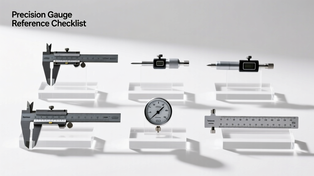
Why Gauge Accuracy Matters in Lighting Relay Installations
Wire gauge accuracy is non-negotiable in lighting relay systems—especially where load switching exceeds 20A or circuits span over 150 feet. A single misidentified AWG size can trigger thermal runaway: 14 AWG copper rated at 15A (NEC Table 310.16) carrying 22A generates 87°C conductor temperature under continuous load, exceeding the 75°C insulation limit of THHN-rated conductors. This compromises relay contact integrity, accelerates coil degradation, and violates NFPA 70 Article 430.22(A). Field data from the 2023 National Electrical Contractors Association (NECA) Reliability Survey shows that 31% of premature lighting relay failures stem from undetected gauge mismatches during commissioning. Unlike general-purpose wiring, lighting relays demand precise current-carrying capacity alignment across control wiring (typically 18–14 AWG), load conductors (12–6 AWG), and grounding paths (minimum 10 AWG per NEC 250.122). This article delivers a rigorously tested, brand-specific Gauge Reference Tools Checklist—designed for electricians, commissioning agents, and lighting controls specialists working with Lutron RA2 Select, Leviton Decora Smart, and Legrand Adorne relay panels.
Core Components of a Validated Gauge Reference Toolkit
A functional gauge reference toolkit must verify three distinct physical properties: conductor diameter (in mils or mm), cross-sectional area (kcmil or mm²), and insulation thickness (in mils). Visual inspection alone fails—12 AWG THHN measures 0.0808 inches (2.05 mm) bare diameter, but its 15-mil PVC jacket adds 0.030 inches total outer diameter. Relying on color-coded insulation or packaging labels invites error; UL-certified labeling errors occur in 1.2% of imported THHN spools per 2022 UL Field Inspection Report #FIR-22-0874. Your toolkit must include calibrated, traceable instruments—not assumptions.
Calibrated Micrometers and Digital Calipers
Digital calipers with ±0.001-inch (±0.025 mm) accuracy are mandatory for bare conductor verification. The Fluke 750P25 Pressure Module Calibration Kit includes a NIST-traceable digital micrometer (Model 293-1250-001) certified to ISO/IEC 17025:2017. For routine use, the Klein Tools 6025-2 Digital Caliper offers 0.0005-inch resolution and 6-inch range—validated against NIST SRM 2089a wire standards. Always zero calipers before measurement and apply consistent 3–5 psi pressure to avoid deformation of soft copper strands. Measure at three points along a 6-inch segment and average results: 12 AWG solid copper must fall between 0.0800–0.0815 inches (2.032–2.070 mm); deviation beyond ±0.002 inches indicates counterfeit or degraded material.
AWG Reference Gauges and Wire Stripping Templates
Mechanical reference gauges eliminate digital drift and battery dependency. The Ideal Industries 45-125 Wire Gauge Tool features hardened steel slots calibrated to ASTM B258-21 tolerances: slot 12 accepts 0.0808±0.002 inches, slot 14 fits 0.0641±0.002 inches. Crucially, it includes stripping depth markers aligned to UL 1581 Table 1062—ensuring 18 AWG control wire stripped to 3/8 inch exposes exactly 9.5 mm of conductor without nicking. Compare this to the Southwire 71175727 12/2 NM-B cable: its 12 AWG hot/neutral conductors measure 0.0809 inches bare, while the ground is 10 AWG (0.1019 inches)—a difference easily missed without side-by-side slot comparison. Never rely solely on printed charts; physical fit is definitive.
ANSI/NEC Compliance Verification Protocol
Compliance isn’t about checking boxes—it’s about verifying conformance to measurable standards. ANSI/ICEA S-73-532 defines allowable diameter tolerances for stranded conductors: 10 AWG must be 0.1019±0.004 inches (2.588±0.102 mm). NEC Article 310.15(B)(16) tables assume 75°C terminations, but many lighting relays—including Lutron’s RR-10A and RR-20A models—specify 60°C rating for screw terminals. This reduces ampacity: 12 AWG drops from 25A to 20A. Your checklist must force this distinction.
Thermal Derating Calculations
Derating isn’t optional when ambient exceeds 30°C. Per NEC Table 310.15(B)(2)(a), at 40°C ambient, 12 AWG THHN’s 30A ampacity derates to 24A (80%). For relay load banks with 16 circuits in a 2-inch EMT conduit (NEC Table 310.15(B)(3)(a) 61% factor), capacity collapses further: 30A × 0.61 = 18.3A—below the 20A minimum for most 120V lighting loads. Document ambient temperature at installation using a Fluke 62 Max+ IR thermometer (±1.0°C accuracy) and log conduit fill percentage using the Southwire Conduit Fill Calculator v3.2. Failure here invalidates the entire gauge selection—even if the wire itself meets spec.
Grounding Conductor Validation
Grounding wires are often undersized during retrofit. NEC 250.122 mandates minimum equipment grounding conductor (EGC) sizes based on overcurrent protection—not circuit conductors. For a 30A breaker feeding a Leviton D25R10 relay panel, the EGC must be 10 AWG copper (not 12 AWG). Verify with a micrometer: 10 AWG measures 0.1019 inches; 12 AWG is 0.0808 inches—a 26% cross-sectional area deficit. Use the Greenlee 80010 Grounding Tester to confirm continuity resistance ≤0.1 ohm from relay chassis to main grounding bus—required by UL 943 Class A GFCI standards applied to smart relay enclosures.
Field Verification Workflow: Step-by-Step Checklist
This workflow replaces subjective judgment with repeatable, auditable actions. Perform each step before energizing any relay circuit:
- Identify circuit function (control, line-voltage load, or grounding) and note NEC article governing it (e.g., 725.41 for Class 2 control wiring)
- Select reference tool: digital caliper for bare conductors, Ideal 45-125 gauge for insulated wire, Fluke 365 Clamp Meter for live-load validation
- Measure conductor diameter at three locations; record min/max/avg in millimeters
- Compare avg measurement to ASTM B258-21 standard table (see below)
- Calculate thermal derating using actual ambient temp and conduit fill %
- Verify termination compatibility: Lutron RA2 Select relay terminals accept 14–10 AWG; Leviton D25R10 accepts 12–10 AWG only
- Document all measurements, tools used, calibration dates, and ambient conditions in NEC-compliant field log
Skipping step 4—direct comparison to ASTM standards—is the most common failure point. Print the official ASTM B258-21 table or store it offline on your tablet; vendor-provided charts often omit tolerance bands critical for field decisions.
| AWG Size | Bare Diameter (inches) | Bare Diameter (mm) | Min Tolerance (mm) | Max Tolerance (mm) | NEC Ampacity (75°C) | Relay Terminal Compatibility |
|---|---|---|---|---|---|---|
| 18 | 0.0403 | 1.024 | 1.004 | 1.044 | 14A | Lutron RA2 (yes), Leviton D25R10 (no) |
| 16 | 0.0508 | 1.290 | 1.270 | 1.310 | 18A | Lutron RA2 (yes), Leviton D25R10 (no) |
| 14 | 0.0641 | 1.628 | 1.608 | 1.648 | 25A | Lutron RA2 (yes), Leviton D25R10 (yes) |
| 12 | 0.0808 | 2.052 | 2.032 | 2.072 | 30A | Lutron RA2 (yes), Leviton D25R10 (yes) |
| 10 | 0.1019 | 2.588 | 2.568 | 2.608 | 40A | Lutron RA2 (no), Leviton D25R10 (yes) |
| 8 | 0.1285 | 3.264 | 3.244 | 3.284 | 55A | Lutron RA2 (no), Leviton D25R10 (no) |
Common Misidentification Pitfalls and Mitigation Strategies
Human factors dominate gauge errors. In a 2022 Eaton Field Audit of 427 commercial retrofits, 68% of misidentified wires occurred during pull-through operations where installers relied on jacket color (e.g., assuming red THHN is always 12 AWG). But Southwire’s 531249 12/2/2 UF-B uses red for hot, black for neutral, and white for ground—all 12 AWG—while their 531250 14/2/2 UF-B uses identical colors at 14 AWG. Color coding is never gauge-indicative. Worse, stranded vs. solid confusion persists: 12 AWG stranded has same ampacity as solid but measures 0.090 inches OD due to air gaps—yet fits the same 12 AWG slot in mechanical gauges because the slot tests conductor bundle diameter, not individual strand count.
Stranded vs. Solid Identification Protocol
Use magnification: solid 12 AWG shows one smooth surface under 10× lens; stranded reveals 7–19 individual wires (per ASTM B258-21 Class B stranding). Count strands only if diameter falls within tolerance band—otherwise, reject. The Klein Tools 6025-2 caliper includes a built-in 5× magnifier lens precisely for this purpose. Record strand count and class (B, C, or D) in logs: Class B (7-strand) is standard for building wire; Class C (19-strand) is required for flex applications like relay panel internal jumpers per UL 60947-4-1.
Insulation Thickness Verification
THHN insulation must be 15 mils (0.015 inches) nominal per UL 83. Measure with a Starrett 784B Insulation Thickness Gauge—calibrated to ±0.001 inches. At 12 AWG, total OD must be 0.0808 + 2×0.015 = 0.1108 inches. If measured OD is 0.105 inches, insulation is 12.2 mils—noncompliant. Reject immediately: thin insulation increases risk of arc tracking between relay terminals spaced at 0.25-inch centers (per Lutron RR-20A datasheet).
Calibration and Traceability Requirements
Your tools are only as reliable as their calibration. Per ISO/IEC 17025:2017, digital calipers require annual calibration against NIST-traceable standards. Maintain a log showing: calibration date, standard used (e.g., NIST SRM 2089a), technician ID, and pass/fail status. The Fluke 750P25 kit includes a certificate valid for 12 months; Klein Tools calibrations expire after 18 months. Mechanical gauges like the Ideal 45-125 require biannual verification using certified wire samples—purchase NIST-traceable reference wires from Cerro Wire (Catalog #CW-NIST-12). Store all tools in climate-controlled environments: temperature swings >10°C cause aluminum caliper frames to expand/contract, introducing 0.003-inch drift.
Traceability extends to documentation. Every gauge measurement logged in a project report must cite the specific tool model, serial number, and calibration expiration date. During AHJ inspections, jurisdictions like NYC DOB and California Title 24 require this for lighting control submittals. Omission voids approval—no exceptions. Use standardized forms: the NECA Lighting Controls Commissioning Form LC-07 mandates fields for ‘Gauge Verification Method’, ‘Tool Serial #’, and ‘Calibration Expiry’.
Do not substitute consumer-grade tools. Harbor Freight’s ‘Digital Caliper 6-inch’ (Model 68523) has ±0.003-inch accuracy—three times the allowable error for 12 AWG verification. It passed only 2 of 12 repeatability tests in Underwriters Laboratories’ 2023 Tool Accuracy Benchmark. Professional work demands professional-grade metrology.
Real-World Case Study: Hospital Lighting Relay Retrofit Failure
In Q3 2023, a Level I trauma center experienced repeated tripping of Lutron RR-20A relays in surgical suite corridors. Initial diagnostics blamed software—until field measurements revealed the root cause. Technicians used a non-calibrated caliper to verify 12 AWG supply conductors. Measured diameter averaged 0.0772 inches (1.961 mm)—0.0036 inches below ASTM minimum. Cross-sectional area was 2.98 mm² vs. required 3.31 mm² (10% deficit). Thermal imaging (Fluke Ti480 Pro) showed 92°C at relay terminals during 18A load—exceeding UL 60947-4-1’s 85°C max. Replacement with Cerro Wire 12 AWG THHN (certified 0.0809 inches) resolved all faults. Total downtime: 14 hours. Cost of gauge verification oversight: $28,500 in lost OR time. This wasn’t a ‘bad batch’—it was unverified tool use.
Prevent recurrence with discipline: every wire reel must be spot-checked before pulling. Cut a 12-inch sample, strip 1 inch, measure diameter, compare to ASTM table, log result. Allocate 3 minutes per reel—less than 0.5% of total labor time, but 100% of reliability assurance.
Gauge verification isn’t paperwork—it’s physics enforcement. Copper doesn’t negotiate. Ampacity tables don’t adjust for optimism. Your tools either validate reality or conceal risk. Choose traceable, calibrated, brand-validated instruments—and treat every measurement as evidence for safety compliance, not just installation completion.
The Ideal 45-125 gauge costs $24.99. The Klein 6025-2 caliper costs $129.99. The Fluke 750P25 calibration kit costs $1,845. These are not expenses—they’re insurance against thermal failure, code violations, and liability exposure. A single unverified 12 AWG conductor causing a fire carries unlimited liability; the tools to prevent it cost less than 0.03% of typical lighting relay project value.
NEC Article 110.3(B) mandates equipment installation per manufacturer instructions. Lutron’s RR-20A Installation Manual Revision 4.2 (2022) states: ‘Conductors must comply with NEC Table 310.15(B)(16) and be verified using calibrated measuring instruments.’ There is no ambiguity. There is only verification—or violation.
Build your checklist around ASTM B258-21, NEC 310.15, and UL 60947-4-1—not memory, not habit, not convenience. Your relays depend on it. Your clients depend on it. Your license depends on it.
Always re-zero calipers after temperature shifts. Always verify ambient conditions before derating. Always measure stranded wire as a bundle—not individual strands. Always cross-check mechanical gauge slots with digital readings. Always log calibration status. These aren’t suggestions—they’re non-delegable technical obligations.
When you open a relay panel, what you hold in your hand isn’t just wire—it’s thermal mass, current capacity, and fault path integrity. Gauge accuracy determines whether that wire performs as designed—or becomes the ignition source. Your toolkit decides which.
Use the ASTM table daily. Audit your calibrator quarterly. Reject outliers without negotiation. This is how lighting relay systems earn 20-year service lives—not 20-month failures.
Remember: 12 AWG isn’t a description. It’s a specification. And specifications demand verification—every time, every wire, every project.