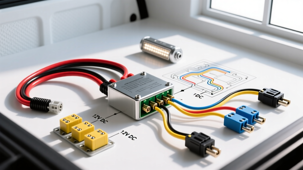
Project Overview: Adapting Commercial Wet-Location LEDs for 12V DC
When outfitting heavy-duty work trucks, tow rigs, or overland expedition vehicles, commercial-grade lighting often outperforms standard automotive off-road brands in longevity and thermal management. The Lithonia OLFL (Outdoor LED Flood Light) series, for example, offers exceptional IP67-rated wet-location durability and high-lumen COB arrays. However, integrating these fixtures into a 12V DC automotive electrical system requires bypassing the factory AC driver and building a custom automotive relay harness. This guide details the exact modification process, translating the standard Lithonia lighting LED wiring diagram into a robust, 12V DC truck bed relay upgrade.
Decoding the Lithonia Lighting LED Wiring Diagram for Automotive Use
The factory Lithonia lighting LED wiring diagram is designed for 120V-277V AC commercial applications. Inside the fixture housing, the line and neutral wires connect to an internal constant-current LED driver (often a Meanwell HLG series). To adapt this for a Ford F-350 or Ram 3500 truck bed work-light setup, we must remove the AC driver and inject 12V DC power directly into a compatible automotive DC driver, or wire a 12V DC constant-current driver to the LED board's DC input pads.
The AC to DC Driver Conversion
Before touching any automotive wiring, the fixture must be prepped. Open the sealed driver compartment on the Lithonia housing. Disconnect the AC line (black), neutral (white), and ground (green) from the terminal block. Locate the DC output wires (typically red for V+ and black for V-) leading to the LED SMD/COB board. You will splice a 12V DC automotive constant-current driver to these DC pads. Ensure the replacement driver matches the milliampere (mA) requirement of the Lithonia LED array—usually 700mA or 1050mA for high-output commercial flood arrays.
Required Materials and Wire Specifications
Commercial truck environments demand vibration-resistant and moisture-proof materials. We adhere to SAE J1128 standards for low-tension primary cable to ensure the wiring withstands under-hood and under-chassis temperatures.
| Component | Specification | Function / Notes |
|---|---|---|
| Main Power Wire | 10 AWG TXL (Cross-linked) | Battery to Relay (Pin 30) & Relay to Load (Pin 87). High heat resistance. |
| Trigger Wire | 16 AWG GXL | Cab switch to Relay (Pin 86). Low current draw. |
| Ground Wire | 10 AWG TXL | Relay (Pin 85) and Load Ground to chassis. |
| Relay | ISO Mini 4-Pin (Bosch Style) | Rated 40A. Follows Bosch ISO 7588 pinout standards. |
| Connectors | Delphi Weather-Pack (2 & 3 cavity) | Silicone seals prevent capillary action and moisture ingress. |
| Overcurrent Protection | 15A ATO Blade Fuse (Waterproof) | Placed within 8 inches of the positive battery terminal. |
Step-by-Step 4-Pin Relay Harness Integration
With the fixture prepped and the internal driver swapped to accept 12V DC, the next phase is building the automotive relay harness. This isolates the high-current draw of the Lithonia LEDs from the vehicle's delicate interior switchgear.
Step 1: Building the ISO Mini Relay Harness
We utilize a standard 4-pin ISO mini relay. The pinout is critical for a safe modification:
- Pin 30 (Common / Input): Connect to the 10 AWG main power wire from the battery positive terminal.
- Pin 87 (Normally Open / Output): Connect to the 10 AWG positive wire leading to the Lithonia LED fixture's DC driver input.
- Pin 86 (Coil Positive): Connect to the 16 AWG trigger wire routed from the cab-mounted toggle switch.
- Pin 85 (Coil Ground): Connect to a clean, bare-metal chassis ground using a ring terminal and star washer.
Use a relay socket with integrated flyback diodes. When the relay coil collapses, it generates a voltage spike that can backfeed into modern CAN-bus systems or damage solid-state cab switches. The diode suppresses this transient spike.
Step 2: Routing, Fusing, and Termination
Route the 10 AWG main power wire from the battery through the firewall or along the frame rail. According to standard automotive electrical practices, the 15A waterproof ATO fuse holder must be installed within 8 inches of the battery terminal. If the wire shorts against the chassis before the relay, the fuse will blow instantly, preventing a thermal event.
At the truck bed, terminate the connection to the Lithonia fixture using a 2-cavity Delphi Weather-Pack connector. This allows you to detach the light for bed liner maintenance or vehicle servicing without cutting wires. Seal the rear of the Weather-Pack cavities with dielectric grease and heat-shrink tubing to prevent oxidation.
Step 3: Trigger Circuit and Switch Wiring
For the trigger circuit, tap into an ignition-switched 12V+ source in the cab (such as the upfitter switch bank in a Ford Super Duty or the aux switches in a Ram). Run the 16 AWG GXL wire to a heavy-duty marine-grade toggle switch. From the switch output, route the wire through the firewall grommet to Pin 86 on the relay. This ensures the Lithonia work lights can only be activated when the key is in the 'ON' or 'RUN' position, preventing accidental battery drain.
Troubleshooting Decision Tree: Common Modification Failures
Adapting commercial Lithonia lighting LED fixtures to DC automotive systems can introduce unique electrical anomalies. Use this decision tree to diagnose issues post-installation.
Symptom: LEDs Flicker or Pulse at Idle
- Cause 1: Alternator ripple voltage exceeding the DC driver's tolerance. Fix: Install a 12V DC line filter capacitor (10,000µF) parallel to the power input at the fixture.
- Cause 2: Voltage drop on the 10 AWG run. If the truck bed run exceeds 15 feet, voltage drop may starve the constant-current driver. Fix: Upgrade the main power and ground runs to 8 AWG TXL wire.
Symptom: Relay Chatters or Fails to Disengage
- Cause: Backfeed voltage from a shared CAN-bus circuit or LED tail light module. Fix: Verify the relay socket has an internal suppression diode. Ensure Pin 85 is grounded directly to the chassis, not daisy-chained to the light fixture's ground.
Symptom: Fixture Trips GFCI or Blows Fuse Instantly
- Cause: Inrush current spike. Commercial LED drivers draw a massive surge of current for milliseconds when charging internal capacitors. Fix: Switch from a standard fast-acting ATO blade fuse to a 15A Slow-Blow (Time-Delay) fuse to accommodate the inrush curve without nuisance tripping.
Final Inspection and Torque Specs
Before sealing the Lithonia housing, verify all solder joints on the DC driver swap are covered with adhesive-lined marine heat shrink. When mounting the fixture to the aluminum or steel truck bed rack, use nylon isolation washers between the stainless steel mounting bolts and the aluminum fixture housing. This prevents galvanic corrosion, which can compromise the fixture's IP67 ground seal over time. Torque the mounting hardware to 12 Nm (8.8 lb-ft) to ensure a rigid mount without cracking the cast-aluminum heat sink fins.