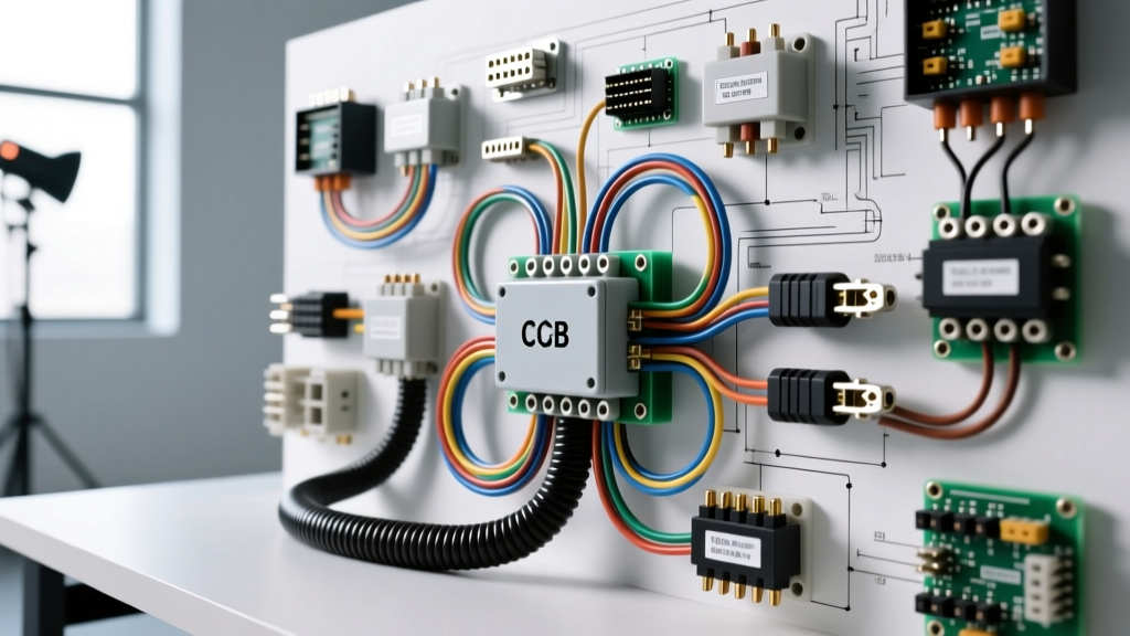
The 'Heart' of the Vehicle: Understanding the Power Distribution Core
In advanced automotive architecture, the Central Junction Box (CJB) and Battery Junction Box (BJB) function as the 'heart' of the vehicle's electrical system. These main power distribution centers act as the primary ventricles, pumping high-current DC power and multiplexed CAN-bus data signals through the miles of copper wiring harnesses. When diagnosticians and enthusiasts ask what causes electrical problems in the heart of a modern vehicle, they are almost always chasing high-resistance faults, galvanic corrosion, and parasitic draws originating at these main distribution hubs. Understanding the anatomy of the CJB, along with strict adherence to safety protocols, is mandatory for accurate fault-finding.
Critical Safety Warnings Before Probing the Core
Before connecting a multimeter to the main power distribution hub, technicians must respect the extreme energy potential stored within the vehicle's 'heart.' Ignoring these safety parameters can result in severe arc flashes, destroyed Electronic Control Units (ECUs), or accidental deployment of pyrotechnic safety devices.
- High-Current Arc Hazards: The main battery feed cables entering the BJB are typically 0 AWG (53.5 mm²) or 2 AWG, capable of delivering over 800 Cold Cranking Amps (CCA). A slipped probe can cause an immediate dead-short, melting copper and causing third-degree burns. Always use insulated tools and wear Class 0 electrical gloves when working near the main MIDI mega-fuses.
- SRS Capacitor Drain Time: The CJB often routes power to the Restraints Control Module (RCM). Disconnecting the negative battery terminal is not enough to eliminate shock or deployment risks. You must wait a minimum of 10 to 15 minutes for the Diagnostic Energy Reserve Module (DERM) capacitors to discharge before probing any yellow 2-pin or 4-pin Delphi GT 280 series SRS connectors.
- Multimeter CAT Ratings: Never use a standard electronics multimeter for automotive high-current testing. Ensure your Digital Multimeter (DMM) is rated at least CAT III 1000V or CAT IV 600V to prevent internal meter arcing when measuring voltage drops across the main starter and alternator feeds.
What Causes Electrical Problems in the Heart of Your Wiring?
Faults within the central junction boxes rarely occur randomly. They are usually the result of environmental ingress, thermal cycling, or improper aftermarket modifications. Below is a diagnostic decision tree to help isolate the root cause of core electrical failures.
Symptom-Cause-Fix Decision Tree
- Symptom: Intermittent no-crank condition, dashboard flickering, and multiple U-codes (e.g., U0100 Lost Communication with ECM) stored across unrelated modules.
- Cause: Voltage drop across the main 150A or 200A MIDI mega-fuse in the BJB due to terminal fretting corrosion. Thermal cycling causes the copper terminals to expand and contract, breaking the oxide layer and creating high resistance.
- Fix: Perform a dynamic voltage drop test under load. If the drop exceeds 0.1V across the fuse, replace the fuse and clean the female spade terminals using a nylon terminal brush. Apply a thin layer of non-conductive dielectric grease to prevent moisture ingress.
- Symptom: Parasitic battery drain exceeding 50mA after the vehicle enters sleep mode (typically 20-45 minutes post-ignition off).
- Cause: Corrosion or moisture ingress inside the CJB causing micro-shorting between adjacent 18 AWG or 20 AWG CAN-bus or ignition-switched circuits. This keeps modules awake by 'ghosting' a 12V reference signal.
- Fix: Inspect the CJB weatherpack seals and firewall grommets. Perform a thermal imaging scan on the CJB in a dark, cool environment to locate the specific circuit generating heat from the parasitic draw, then isolate the faulty module or repair the harness.
Common Mistakes Technicians Make at the Main Power Hub
When diagnosing the heart of the electrical system, the methodology is just as important as the tools. Avoid these catastrophic diagnostic errors:
1. The Continuity Test Fallacy
One of the most dangerous mistakes is relying on an Ohmmeter continuity test to verify the health of high-current CJB feeds. A single surviving strand of a frayed 4 AWG wire can show 0.01 ohms of resistance on a DMM, indicating a 'good' circuit. However, under a 120A alternator load, that single strand will act as a resistor, overheat, and melt the connector housing. Always use dynamic voltage drop testing under load to evaluate high-current circuits. According to Delphi Technologies Electrical Architecture guidelines, a healthy high-current connection should exhibit less than 0.1V drop per connection point.
2. Piercing Wire Insulation with T-Pins
Piercing the insulation of wires leading into the CJB with sewing needles or standard T-pins introduces a direct pathway for moisture to reach the copper strands. This leads to copper oxide formation (green crust) which migrates under the insulation via capillary action, eventually causing an open circuit inside the harness. Always back-probe connectors using the correct proprietary terminal release tools and dedicated back-probe pins that match the connector cavity size (e.g., TE Connectivity MQS or Yazaki 0.64mm unsealed terminals).
3. Using Incandescent Test Lights on Data Circuits
The CJB routes high-speed CAN-bus (Controller Area Network) twisted pairs, typically 18 AWG with an impedance of 120 ohms. Using a standard 12V incandescent test light to probe CAN-High or CAN-Low circuits at the CJB can draw excessive current, instantly destroying the delicate CAN transceiver inside the ECU. Furthermore, the electromagnetic interference (EMI) generated by the test light's filament can corrupt data packets, causing phantom faults. Always use a high-impedance DMM or a dedicated automotive oscilloscope to probe data lines, adhering to SAE J1113 standards for Electromagnetic Compatibility.
CJB and BJB Specification Reference Chart
Use the following reference table when verifying wire gauges, terminal types, and torque specifications at the main power distribution hubs. Specifications are generalized for modern North American domestic and import architectures.
| Circuit Function | Wire Gauge (AWG) | Typical Wire Color | Connector / Terminal Type | Torque Spec / Pin Tension |
|---|---|---|---|---|
| Main Battery Feed (BJB to CJB) | 0 AWG to 2 AWG | Black / Red (XLPE Insulated) | M8 / M10 Ring Terminal | 10 - 12 Nm |
| Alternator Output Feed | 4 AWG to 6 AWG | Orange / Black Stripe | M6 Ring Terminal / Metri-Pack 800 | 8 - 10 Nm |
| CAN-Bus High / Low (Twisted Pair) | 18 AWG to 20 AWG | White/Blue & White/Yellow | Delphi Metri-Pack 150 (Sealed) | Min 5N Pin Retention |
| SRS / Airbag Power Feed | 18 AWG | Yellow (Outer Insulation) | GT 280 Series (w/ Shorting Bar) | Min 4N Pin Retention |
| Ignition Switched (Run/Start) | 14 AWG to 16 AWG | White / Light Green | Metri-Pack 280 Female Spade | Min 6N Pin Retention |
Advanced Troubleshooting: Galvanic Corrosion in the BJB
A frequent culprit behind the question of what causes electrical problems in the heart of the vehicle's charging system is galvanic corrosion. Because the BJB is mounted directly on or adjacent to the 12V lead-acid or AGM battery, it is constantly exposed to sulfuric acid outgassing. When this acidic vapor mixes with ambient humidity and settles on the exposed copper and aluminum bus bars inside the BJB, it creates an electrolytic cell. This accelerates galvanic corrosion, eating away at the metal and creating massive voltage drops.
To combat this, OEM engineers coat BJB bus bars with a tin or nickel plating. However, if a technician scratches this plating during a fuse replacement, the raw copper is exposed, and corrosion will rapidly form. When servicing the BJB, always neutralize the area with a baking soda and distilled water solution, dry thoroughly with compressed air, and apply a dedicated electrical contact protectant (such as CRC Di-Electric Grease or NO-OX-ID A-Special) to all exposed bus bars and mega-fuse blades.
Conclusion
Diagnosing the core of a vehicle's electrical system requires a shift from simple component swapping to systematic, physics-based electrical analysis. By understanding the architecture of the CJB and BJB, respecting the safety hazards of high-current and SRS circuits, and avoiding destructive probing methods, you can accurately isolate the faults that plague the heart of the vehicle. For further diagnostic procedures and wiring schematic interpretation, consult your OEM-specific service manuals and Ford Motorcraft Fleet Maintenance resources or equivalent manufacturer portals.