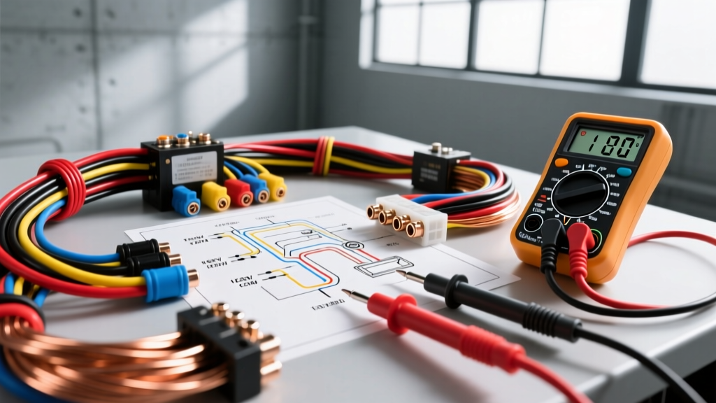
The Paradigm Shift: From 120V AC to 12V DC
Many DIY mechanics begin their electrical journey by troubleshooting household electrical problems. Replacing a standard 120V AC duplex receptacle or wiring a single-pole switch builds foundational confidence. However, when these same DIYers transition to automotive 12V DC systems, they often encounter frustrating diagnostic dead-ends. The fundamental physics of electricity remain the same—Ohm’s Law (V=IR) governs both your living room and your engine bay—but the application, wire sizing, grounding topologies, and failure modes are drastically different.
In a household alternating current (AC) system, you are dealing with 120V (or 240V) at 60Hz. The high voltage means that current (Amperage) remains relatively low for a given wattage. In an automotive direct current (DC) system, the nominal voltage is 12.6V at rest and roughly 14.2V to 14.4V when the alternator is charging. Because the voltage is so low, the current required to perform the same amount of work is exponentially higher. A 1,440W space heater in your home draws 12 Amps on a standard 15A circuit. A 1,440W starter motor in your truck draws over 100 Amps. This massive difference in current dictates everything from wire gauge selection to connector pin sizing.
Wire Gauge and Insulation: THHN vs. GXL
When troubleshooting household electrical problems, you are accustomed to pulling Romex (NM-B) cable or running THHN wire through conduit. Household wiring is sized according to the National Electrical Code (NEC / NFPA 70). A 14 AWG copper wire is rated for 15 Amps, while 12 AWG is rated for 20 Amps.
Automotive wiring, governed by standards like SAE J1128, uses entirely different insulation types and ampacity derating scales. Automotive wire (such as GXL, SXL, or TXL) features thin-wall, cross-linked polyethylene insulation designed to withstand under-hood temperatures of 125°C to 150°C, as well as exposure to oil, fuel, and road salt. Because automotive wire is often bundled tightly in looms, heat dissipation is reduced, meaning ampacity ratings differ from household wire.
AWG Comparison: Household (NEC) vs. Automotive (SAE)
| Wire Gauge (AWG) | Household (THHN / NM-B) Ampacity | Automotive (GXL / SXL) Single Wire Ampacity | Common Automotive Application |
|---|---|---|---|
| 18 AWG | Not permitted for 120V branch | 6A - 8A | ECU sensors, CAN bus lines, LED marker lights |
| 16 AWG | Not permitted for 120V branch | 10A - 12A | Radio power, interior lighting, horn circuits |
| 14 AWG | 15 Amps (120V AC) | 15A - 20A | Headlight feeds, power window motors, ABS valves |
| 12 AWG | 20 Amps (120V AC) | 25A - 30A | Fuel pump power, high-amperage cooling fans |
| 10 AWG | 30 Amps (240V AC Dryer) | 40A - 50A | Main ignition feeds, heavy-duty accessory relays |
| 4 AWG | 85 Amps (Copper THHN) | 120A - 150A | Battery to starter solenoid, high-output alternator |
Note: Never substitute household THHN wire for under-hood automotive repairs. THHN insulation will melt on exhaust manifolds and degrade rapidly when exposed to engine oil.
Grounding Topologies: Earth vs. Chassis
In residential wiring, the grounding system is a dedicated safety net. You have a 'Hot' (Black), a 'Neutral' (White) which carries the return current, and a 'Ground' (Bare/Green) which only carries current during a fault to trip the breaker. The ground is physically bonded to an earth rod.
In a vehicle, the entire steel or aluminum chassis acts as the return path to the battery's negative terminal. This is known as a 'Common Ground' or 'Chassis Ground' system. There is no dedicated neutral wire. The power wire (often Red, Yellow, or Pink) carries the 12V to the load, and the ground wire (often Black or Brown) bolts directly to the nearest metal chassis point. When troubleshooting household electrical problems, a loose ground wire simply means your safety system is compromised. In a car, a loose G104 chassis ground point means the fuel pump won't run, the ECM will throw a U0100 CAN-bus code, and the engine will stall. Always verify chassis ground points for rust, galvanic corrosion, and loose torque specs before condemning expensive electronic control modules.
The Multimeter Transition: Mastering the Voltage Drop Test
The most valuable tool for auto electrical diagnosis is the digital multimeter (DMM). While you may use a DMM to check for 120V continuity or outlet polarity at home, automotive diagnostics relies heavily on the Voltage Drop Test. Because automotive systems operate on a mere 12V, even a small amount of unwanted resistance in a corroded connector will starve a component of the voltage it needs to operate.
According to Fluke's automotive diagnostic guidelines, testing a circuit for voltage drop is vastly superior to testing for resistance with the power off. Resistance tests use the multimeter's tiny internal battery and cannot detect failures that only occur under heavy load.
Step-by-Step: Starter Circuit Voltage Drop
If you have a 'No-Crank' condition, do not just replace the starter. Perform a voltage drop test on the 4 AWG positive and negative battery cables while an assistant turns the key to the 'CRANK' position.
- Set your DMM to DC Volts (V⎓).
- Positive Side Drop: Place the Red probe on the battery positive post (not the clamp, the actual lead post) and the Black probe on the starter motor B+ terminal. Crank the engine. A reading above 0.5V indicates high resistance in the positive cable, battery clamps, or solenoid contacts.
- Negative Side Drop: Place the Red probe on the battery negative post and the Black probe on the starter motor mounting bolt (the ground path). Crank the engine. A reading above 0.2V indicates a poor engine block ground or corroded battery negative clamp.
- Total Circuit Drop: The combined voltage drop of the entire starter circuit should not exceed 0.7V. If your battery reads 12.4V at rest, the starter should see at least 11.7V during cranking.
Relays: The Automotive Equivalent of Household Switches
In your home, a 15A single-pole switch directly interrupts the hot wire to a light fixture. In a vehicle, running high-amperage loads (like 55W H11 headlights or dual cooling fans) directly through a dashboard switch would require massive, stiff wiring harnesses and would cause the switch contacts to melt.
Instead, vehicles use electromechanical relays. The standard ISO Mini 4-pin relay is the workhorse of modern automotive wiring. Understanding its pinout is mandatory for any auto electrician:
- Pin 30: Common / Constant 12V Battery Power (Usually fed by a heavy gauge wire and a maxi-fuse).
- Pin 87: Normally Open / Switched Power Output (Feeds the load, e.g., the headlight).
- Pin 85: Relay Coil Ground (Tied to chassis ground or controlled by the ECM/BCM).
- Pin 86: Relay Coil Switched 12V (Triggered by the low-amperage dashboard switch).
When troubleshooting a dead headlight, listen for the relay click. If it clicks, the control side (Pins 85 and 86) is working. Use your multimeter to check for 12V at Pin 30, and verify continuity between Pin 87 and the H11 headlight connector (Pin 2 is typically power, Pin 1 is ground). If the relay does not click, use your DMM to test for 12V at Pin 86 and verify continuity to ground at Pin 85.
Parasitic Draws vs. Tripped Breakers
When a household circuit shorts out, the 15A or 20A thermal-magnetic breaker trips instantly, cutting power and preventing a fire. When an automotive circuit shorts, it blows a blade fuse (ATO, Mini, or Maxi). However, what happens when a car battery dies overnight? This is a parasitic draw.
Modern vehicles have dozens of modules that stay awake for up to 45 minutes after the key is removed. A normal parasitic draw is between 20mA and 50mA (0.020A - 0.050A). To test this, you must set your multimeter to the 10A port, disconnect the negative battery terminal, and place the meter in series between the negative post and the disconnected cable. Wait for the modules to 'sleep'. If the draw remains above 50mA, pull fuses one by one until the draw drops, isolating the offending module (often a glovebox switch, aftermarket alarm, or faulty alternator diode trio).
Summary: Respecting the 12V Environment
While the logic of troubleshooting household electrical problems provides a great foundation in basic circuit theory, automotive diagnostics requires a shift in mindset. You must respect the high-current, low-voltage nature of DC systems, prioritize voltage drop testing over simple continuity checks, and understand that the vehicle's chassis is an active, vital component of the circuit. Equip yourself with SAE-rated GXL wire, quality crimpers, and a reliable DMM, and you will conquer any 12V electrical fault.