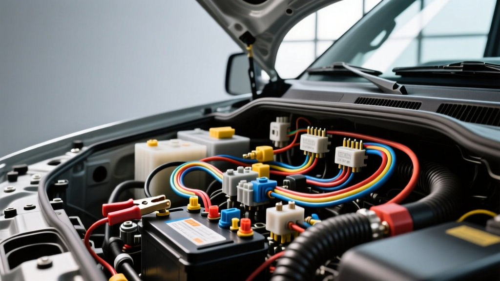
Bridging Automotive Electrical Systems and Agricultural Containment
When outfitting a heavy-duty ranch truck or overland expedition vehicle for remote livestock management, integrating a 12V DC portable fence energizer into the vehicle’s auxiliary electrical system is a highly effective modification. This setup allows ranchers to deploy temporary rotational grazing enclosures directly from the bed of an F-250 or Ram 2500 without relying on standalone, easily stolen lead-acid batteries. However, when the fence fails to hold a charge, many operators mistakenly blame the energizer or the physical fence line. In reality, troubleshooting electric fence problems in these mobile setups almost always requires diagnosing the vehicle-side wiring harness, auxiliary battery isolation relays, and grounding faults.
High-impedance fence energizers draw relatively low continuous amperage (typically 2 to 8 amps) but require pristine, low-resistance voltage delivery to properly step up the 12V DC input into the 5,000 to 10,000-volt output pulses required for livestock containment. A voltage drop of even 1.5 volts at the input terminals can cause the energizer’s internal oscillator to fail or output a weak pulse that livestock will easily breach. This guide details the exact automotive electrical diagnostics required to resolve these issues during your next upgrade project.
Symptom-Cause-Fix Decision Matrix
Use this diagnostic tree to isolate whether the failure lies in the automotive wiring or the agricultural hardware.
| Symptom | Root Cause (Vehicle-Side) | Corrective Action |
|---|---|---|
| Weak pulse (<2kV) on fence line; energizer LED flashes dimly. | Voltage drop >1.0V on 12V feed due to undersized wire or corroded Upfitter relay contacts. | Upgrade to 10 AWG TXL wire; clean or replace Deutsch connector pins; verify battery state of charge. |
| Energizer clicks loudly but animal feels no shock; voltmeter reads 8kV. | False ground path through truck bed liner, trailer hitch, or chassis isolation failure. | Isolate energizer ground from vehicle chassis entirely; deploy dedicated copper-clad earth ground rod. |
| Energizer completely dead; no indicator lights. | Blown MAXI fuse, broken blunt-cut wire, or Upfitter switch logic fault in BCM. | Test continuity at relay control module (RCM); verify 30A fuse integrity; check BCM switch input signal. |
| Truck starting battery dies overnight after fence deployment. | Energizer wired directly to starter battery; lack of dual-battery isolation. | Install Redarc or National Luna smart isolator; rewire energizer to auxiliary deep-cycle AGM or LiFePO4 bank. |
F-Series Super Duty Upfitter Integration
For 2020-2023 Ford F-250 Super Duty trucks, the factory Upfitter switch system is the ideal power source for a 12V energizer. The Upfitter switches are controlled by the Body Control Module (BCM) and utilize under-hood relays, eliminating the need to splice into the truck's primary ignition harness. When wiring an auxiliary power outlet to feed your fence charger, you must tap into the correct blunt-cut wire in the engine bay relay control module (RCM). For a 30A circuit, locate the Upfitter Switch 1 or 2 output wire (typically a white wire with a specific color tracer, as defined in the Ford Body Builder Layout Book).
Because the wire will be routed through the engine bay and exposed to high ambient temperatures, standard PVC automotive wire is insufficient and violates safety standards. You must use SAE J1128 compliant TXL (Cross-linked polyethylene) wire. TXL withstands continuous temperatures up to 125°C and offers a thinner insulation wall for tighter routing through the firewall or bed pass-through grommet.
At the termination point in the truck bed, do not use standard blade connectors or alligator clips. The high-vibration and dusty environment of a ranch truck demands waterproof connections. Crimp the 10 AWG TXL wire using a Deutsch DT04-2P connector. Pin 1 should be your 12V+ feed, and Pin 2 should be your dedicated negative return to the auxiliary battery bus bar.
Anderson Powerpole Integration and Fusing
For quick-disconnect capability, many ranchers terminate their bed-side wiring with a 50A Anderson Powerpole (gray housing) connector. This allows the energizer to be unplugged and moved to a stationary solar setup when the truck is in use. When installing the Anderson connector, you must use a ratcheting crimper (such as the Powerwerx Tri-Power tool) to ensure the 10 AWG or 8 AWG copper strands are cold-welded to the contact pin. A loose crimp will generate immense heat under the continuous 5A pulse load of the energizer, melting the housing and causing a short circuit.
Furthermore, SAE and ABYC guidelines dictate that the primary overcurrent protection device must be located within 18 inches of the power source. Install a 30A MAXI fuse holder directly at the auxiliary battery positive terminal before the wire enters the cab or bed conduit. Do not rely solely on the Upfitter relay's internal protection, as the long wire run to the bed acts as a potential short-circuit hazard if the insulation is chafed by a metal toolbox.
Voltage Drop Testing the Energizer Feed Circuit
The most critical step in troubleshooting electric fence problems related to vehicle power is performing a dynamic voltage drop test. An energizer drawing 5 amps under load will expose high-resistance faults that a static multimeter test will completely miss.
- Set your Fluke 87V multimeter to DC Volts.
- Connect the energizer to a moderate load (a standard fence line with some vegetation contact) and turn it on so it is actively pulsing.
- Place the red probe on the positive terminal of the auxiliary battery and the black probe on the positive input terminal of the energizer.
- Record the voltage drop. A healthy 12V circuit should not exhibit a voltage drop greater than 0.2V across the entire positive feed.
- Repeat the test on the ground side (red probe on energizer negative terminal, black probe on battery negative terminal).
If your drop exceeds 0.2V, you have a resistance fault. This is commonly caused by undersized wire over long distances (e.g., running 14 AWG wire from the engine bay to a bed-mounted toolbox), or by a crimp joint that was improperly executed, leading to stranded wire oxidation inside the Deutsch connector.
The Grounding Dilemma: Chassis vs. Earth
The most frequent catastrophic mistake made during agricultural truck modifications is attempting to use the vehicle's steel chassis, bumper, or trailer hitch receiver as the ground for the electric fence energizer. In standard automotive wiring, the vehicle chassis serves as the ground return path for lighting and accessories. However, an electric fence operates on an entirely different electrical principle.
The energizer sends a high-voltage pulse down the fence wire, through the animal, into the soil, and back to the energizer via an earth ground rod. The vehicle's rubber tires electrically isolate the truck's steel chassis from the earth. If you connect the energizer's ground terminal to the truck's bumper, the pulse has no return path through the soil. The fence will test 'hot' with a digital voltmeter (which measures open-circuit voltage), but the moment an animal touches it, the circuit cannot complete, and the animal will feel little to no shock.
To resolve this, your modification project must include a dedicated grounding system. If the energizer is permanently mounted in the truck bed, you must run a heavy-gauge ground wire (minimum 10 AWG bare copper or green THHN) from the energizer's ground terminal to a copper-clad steel ground rod that is driven into the soil at your deployment site. Keep this ground wire entirely isolated from the truck's metal bed and bed liner.
Parasitic Draw and Battery Isolation
Leaving a 12V fence energizer connected to a truck's starting battery will result in a dead vehicle within a week, as the energizer draws a continuous 2 to 4 amps even when the fence line is perfectly insulated. When designing your upgrade, the energizer must be wired exclusively to an auxiliary deep-cycle AGM or LiFePO4 battery bank. Utilize a smart dual-battery isolator, such as the Redarc SBCI-1225D, which automatically disconnects the auxiliary bank when the alternator voltage drops below 12.7V, ensuring your F-250 or Ram 2500 always has sufficient cranking amps to start the diesel engine, regardless of how long the fence has been running.
Authoritative References
- Ford Motor Company Body Builder Layout Book (F-Series Super Duty) - Upfitter switch pinouts and relay logic.
- SAE Mobilus: J1128 Low Tension Primary Cable Standard - TXL wire temperature and insulation requirements.
- Gallagher Fencing Systems Technical Manuals - High-impedance pulse dynamics and earth grounding physics.