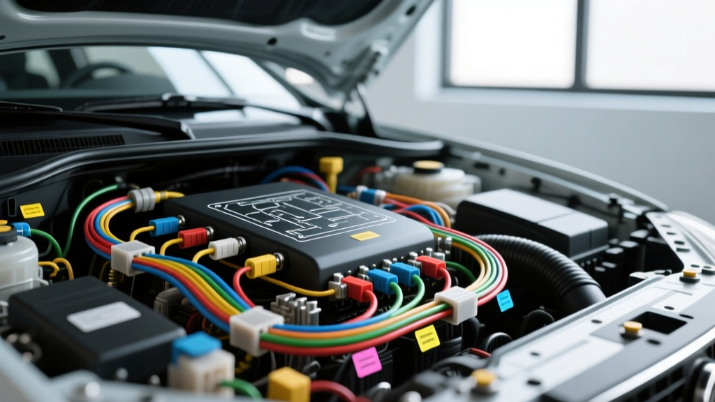
The Automotive "Heart": Why Charging System Failures Are Critical
When a patient asks a cardiologist, "are electrical problems with the heart serious?", the answer is a matter of life and death. The heart’s electrical nodes dictate the rhythm of human survival. In automotive diagnostics, we use the exact same terminology for a vehicle’s charging and starting system. The alternator, battery, and Power Distribution Center (PDC) form the "heart" of your car’s electrical network. When this system suffers from voltage drop, parasitic drain, or internal diode failure, the vehicle’s vital signs—CAN bus network stability, fuel injector pulse width, and ignition coil dwell time—immediately degrade.
If you are experiencing dimming headlights, erratic transmission shifting, or OBD-II codes like U0100 (Lost Communication with ECM), your vehicle’s heart is failing. This practical how-to installation guide will walk you through diagnosing a weak charging system and upgrading to a High-Output Alternator and Auxiliary Battery setup, using the ubiquitous GM LS/LT platform (AD244 alternator generation) as our baseline reference.
Phase 1: Diagnosing the Failing Heart
Before ripping out components, you must confirm the diagnosis. A failing alternator often mimics a bad battery or a parasitic draw. According to Haynes Manual Alternator Testing Procedures, you must perform a voltage drop test under load.
- Baseline Voltage: With the engine off, measure battery voltage at the posts. A healthy AGM battery should read 12.6V to 12.8V.
- Charge Side Voltage Drop: Start the engine and turn on high-beam headlights and the HVAC blower to max. Place your multimeter’s red lead on the alternator B+ terminal and the black lead on the battery positive post. A reading above 0.15V indicates excessive resistance in the charge wire or a corroded fuse link.
- Ground Side Voltage Drop: Move the black lead to the alternator case and the red lead to the battery negative post. Readings above 0.10V mean the alternator is not properly grounded to the engine block.
- PCM Sense Wire Verification: Back-probe the alternator’s sense pin (Pin D on GM AD244). If the voltage at this pin is more than 0.2V lower than the battery post voltage, the PCM is receiving false data and will overcompensate, leading to premature alternator failure.
Phase 2: Sizing Your Vehicle’s New Power Core
Upgrading your vehicle’s heart requires matching alternator output to your actual electrical load. Installing a 250A alternator on a stock vehicle is useless if the wiring cannot handle the amperage. Consult the SAE J1141 Wiring and Connector Standards for proper thermal management.
| Electrical Component | Average Draw (Amps) | Peak Draw (Amps) | Wire Gauge Required (10ft run) |
|---|---|---|---|
| ECU / Fuel Injection / Ignition | 25A | 35A | 10 AWG (OEM Harness) |
| Electric Cooling Fans (Dual) | 30A | 55A (Startup) | 8 AWG |
| Off-Road LED Light Bar (50") | 22A | 25A | 10 AWG |
| 12V Air Compressor | 35A | 45A | 8 AWG |
| Electric Winch (12,000 lb) | N/A | 350A+ | 2/0 AWG (Direct to Aux Battery) |
Phase 3: High-Output Alternator Installation (GM AD244 Platform)
For vehicles requiring continuous high amperage (e.g., overlanding rigs, tow vehicles, or mobile command centers), upgrading from the OEM 130A alternator to a 250A aftermarket unit (such as a Mechman or Power Bastards) is mandatory. As noted in the Madelectrical.com Alternator Technical Guide, the sense wire routing is the most critical part of this installation.
Step 1: Upgrading the B+ Charge Wire
The OEM charge wire is typically 4 AWG or 6 AWG, which will melt or cause severe voltage drop at 200+ amps. You must replace the factory charge wire with 1/0 AWG Oxygen-Free Copper (OFC) wire. Route the new 1/0 AWG wire from the alternator B+ terminal directly to the main starter stud or a high-amperage Mega Fuse block located within 18 inches of the battery positive terminal.
Step 2: Rewiring the 4-Pin PCM Connector
The GM AD244 uses a 4-pin connector. When installing a high-output unit, you must ensure the PCM receives accurate data. Use a Deutsch DT 4-pin connector with sealed terminals for reliability.
- Pin A (L-Terminal / Lamp): Usually a Brown wire. This provides the initial excitation voltage to turn the alternator on. It must be connected to a 12V ignition-switched source. Crucial: You must install a 390-ohm, 1/2-watt resistor in parallel with this wire to prevent backfeeding the PCM when the key is off.
- Pin B (F-Terminal / Field): Usually a Gray or Black/White wire. This sends a 5V PWM duty cycle signal back to the PCM regarding alternator load. Connect directly to the PCM alternator control pin.
- Pin C (Phase): Stator output for tachometers. Often unused in modern CAN-bus vehicles; cap and seal if not required.
- Pin D (S-Terminal / Sense): Usually a Red wire. This is the most critical wire. It tells the internal regulator what the battery voltage actually is. Do not leave this plugged into the factory harness if the factory harness has voltage drop. Run a new 14 AWG Red wire directly from Pin D to the positive post of the main battery or the auxiliary battery positive busbar.
Phase 4: Auxiliary Battery & VSR Integration
To protect the main starting battery from deep-cycle depletion by accessories (winches, fridges, inverters), install a secondary Deep Cycle AGM or Lithium (LiFePO4) battery in the engine bay or cargo area, managed by a Voltage Sensitive Relay (VSR) or a continuous-duty solenoid.
Solenoid Wiring (Cole Hersee 24059 / 200A Rating)
- Run 1/0 AWG OFC from the Main Battery Positive to one large copper stud on the solenoid.
- Run 1/0 AWG OFC from the second large copper stud to the Auxiliary Battery Positive.
- Connect the small ignition trigger terminal to a 12V ignition-switched fuse (e.g., windshield wiper fuse) using 12 AWG wire with a 10A inline ATC fuse.
- Ground the solenoid mounting bracket to a clean, bare-metal chassis point using a star washer and anti-oxidant paste (Noalox).
Note: If using a Lithium auxiliary battery, you must use a DC-DC charger (like a Victron Orion) instead of a standard solenoid, as the alternator will see the low internal resistance of the lithium battery and attempt to output maximum amperage continuously, potentially burning out the alternator stator.
Wiring Specifications and Torque Chart
Improper torque on high-amperage terminals is a leading cause of electrical fires and alternator failure. Use a calibrated inch-pound torque wrench for the following connections:
| Connection Point | Hardware Size | Wire Gauge | Terminal Type | Torque Specification |
|---|---|---|---|---|
| Alternator B+ Post | M8 x 1.25 Nut | 1/0 AWG | Copper Ring (3/8") | 89 - 106 lb-in (10 - 12 Nm) |
| Starter Main Stud | M10 x 1.5 Nut | 1/0 AWG | Copper Ring (3/8") | 15 - 20 lb-ft (20 - 27 Nm) |
| Battery Post Clamp | M8 Bolt | 1/0 AWG | Lead/Acid Clamp | 60 - 80 lb-in (7 - 9 Nm) |
| Engine Block Ground | M10 Bolt | 1/0 AWG | Copper Ring (3/8") | 25 - 30 lb-ft (34 - 40 Nm) |
Post-Installation Troubleshooting Decision Tree
After installation, start the vehicle and measure voltage at the battery posts. You should see 13.8V to 14.4V. If the system is malfunctioning, follow this diagnostic tree:
- Symptom: Voltage remains at 12.2V and drops slowly; Battery light is ON.
- Cause: Alternator is not exciting.
- Fix: Check Pin A (Brown wire) for 12V with the key in the "Run" position. Verify the 390-ohm resistor is intact. Check the ignition fuse.
- Symptom: Voltage spikes to 15.5V+ or drops to 12.5V erratically.
- Cause: PCM Sense Wire (Pin D) has voltage drop or is disconnected.
- Fix: Measure voltage at the alternator B+ post, then measure at Pin D inside the connector. If there is a discrepancy, re-route the Pin D Red wire directly to the battery positive post.
- Symptom: Alternator whines, and the B+ terminal is melting.
- Cause: Loose B+ nut or undersized charge wire causing extreme resistance and heat.
- Fix: Immediately shut off the engine. Clean the terminal, ensure you are using 1/0 AWG wire, and torque the M8 nut to exactly 106 lb-in.
Conclusion
So, are electrical problems with the heart serious? In the automotive world, a compromised charging system will strand you, destroy expensive ECM modules via voltage spikes, and leave you without critical accessories when you need them most. By systematically diagnosing voltage drop, correctly sizing your OFC wiring, and adhering to strict PCM pinout and torque specifications, you ensure your vehicle’s electrical heart beats strong for hundreds of thousands of miles.