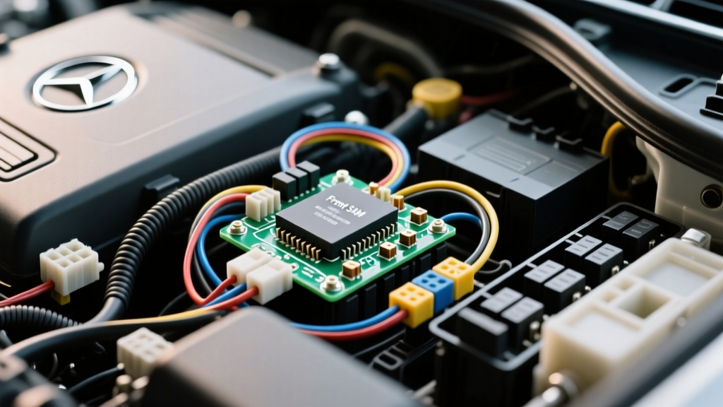
Addressing Electrical Problems Mercedes C Class: The W204 Front SAM Vulnerability
When troubleshooting electrical problems Mercedes C Class vehicles (specifically the 2008-2014 W204 chassis) experience, the root cause frequently traces back to the Front Signal Acquisition Module (SAM). The Front SAM, designated as module A1/1 in Mercedes-Benz wiring schematics, acts as the primary gateway for the engine bay, managing everything from headlamp PWM signals to the windshield wiper motor relays and CAN bus routing. Because of its physical location in the driver-side engine bay fuse compartment, it is highly susceptible to water ingress.
The primary failure mode is not the electronics themselves, but the environmental sealing. When the cowl panel drain tubes become clogged with organic debris, rainwater backs up into the fresh air intake plenum. This water overflows directly onto the SAM enclosure, bypassing the secondary weather seals and causing severe galvanic corrosion on the X3/10 and X4/10 multi-pin connectors. This guide provides a master-level diagnostic decision tree, wiring specifications, and a practical installation procedure for replacing the SAM and repairing the compromised Chassis CAN (CAN C) bus harness.
Diagnostic Decision Tree: Is Your Front SAM Failing?
Before ordering a replacement module, verify the failure mode using this symptom-cause-fix decision tree. The SAM acts as a network node; when it drops off the network or shorts the CAN bus, it creates cascading failures across the vehicle.
- Symptom: Windshield wipers activate at maximum speed and cannot be turned off; ESP and ABS warning lamps illuminate.
- Cause: Water ingress into the X4/10 connector causing a short-to-ground on the wiper relay control circuit or CAN C bus corruption.
- Fix: Inspect X4/10 for copper oxide (green/white crust). Clean with electrical contact cleaner or replace the SAM if internal PCB traces are compromised.
- Symptom: Vehicle exhibits a 'No Crank, No Start' condition, but interior lights and dashboard function normally. U0100 (Lost Communication with ECM) stored in multiple modules.
- Cause: Corrosion on the main power feed (Terminal 30) at the X3/10 connector or complete failure of the SAM's internal voltage regulator, preventing the wake-up signal from reaching the Engine Control Unit (ME).
- Fix: Perform a voltage drop test on the main power feed. If voltage drop exceeds 0.2V under load, repair the harness and replace the SAM.
- Symptom: Intermittent interior lighting flickering, accompanied by a parasitic battery drain exceeding 150mA after the vehicle enters sleep mode.
- Cause: Moisture inside the SAM housing creating a high-resistance leakage path across the Terminal 15R (accessory) or Terminal 15 (ignition) relay outputs, preventing the vehicle's CAN network from entering quiescent sleep mode.
- Fix: Replace the SAM and install updated cowl drain valves to prevent recurrence.
Front SAM and CAN Bus Wiring Specifications
Accurate diagnosis requires understanding the specific pinouts of the Front SAM. The module utilizes three primary connectors. Below are the critical pins related to power, ground, and the High-Speed Chassis CAN bus (CAN C). For deeper physical layer specifications regarding twisted pair impedance and termination, refer to the SAE J2284 High-Speed CAN Standard.
| Connector ID | Pin Number | Wire Color | AWG / mm² | Circuit Function |
|---|---|---|---|---|
| X3/10 | 1 | Red | 12 AWG (4.0 mm²) | Terminal 30 (Constant Battery Power) |
| X3/10 | 10 | Brown | 12 AWG (4.0 mm²) | Ground (Chassis Earth via Z-point) |
| X4/10 | 14 | Green | 20 AWG (0.5 mm²) | CAN C High (Chassis Network) |
| X4/10 | 15 | Green/Black | 20 AWG (0.5 mm²) | CAN C Low (Chassis Network) |
| X4/10 | 7 | Yellow/Red | 18 AWG (0.75 mm²) | Terminal 15R (Accessory Wake-Up) |
Step-by-Step SAM Removal and Harness Repair Installation
Replacing the Front SAM is not a simple plug-and-play procedure. It requires meticulous harness preparation and proprietary software coding. Follow these installation steps to ensure a lasting repair.
Step 1: Battery Isolation and Safety Protocols
Disconnect the negative battery terminal in the trunk (10mm nut, torque to 15 Nm upon reconnection). Wait a minimum of 15 minutes before touching the SAM connectors. This allows the SRS (Supplemental Restraint System) control module and the high-capacity capacitors within the SAM to discharge completely, preventing accidental airbag deployment or module bricking.
Step 2: Cowl Panel and SAM Enclosure Extraction
- Remove the driver-side wiper arm using a specialized puller to avoid damaging the cowl paint.
- Unclip the plastic cowl panel retaining tabs and lift the panel away from the windshield base.
- Remove the three T20 Torx screws securing the SAM weather cover. Inspect the foam seal; if it is compressed or brittle, it must be replaced (Part # 204-546-01-82).
- Disconnect the three main harness connectors (X3/10, X4/10, X5/10) by releasing the secondary locking tabs and pulling the lever locks upward.
- Remove the two M6 mounting nuts securing the SAM to the chassis bracket (Torque spec: 5 Nm).
Step 3: CAN Bus Harness Repair and Splicing
If the X4/10 connector pins 14 and 15 show signs of green copper oxide corrosion, the damage has likely wicked up the wire via capillary action. You must cut back the harness at least 4 inches past the visible corrosion.
- Stripping: Use precision wire strippers to remove 5mm of insulation from the 20 AWG (0.5 mm²) CAN C wires. Do not nick the copper strands, as this alters the characteristic 120-ohm impedance of the twisted pair.
- Splicing: Use MIL-SPEC M81714/12 solder sleeves with pre-installed heat shrink. Slide the adhesive-lined heat shrink over the wire before soldering.
- Sealing: Apply heat evenly until the solder ring melts and the adhesive lining oozes from the ends of the shrink tube. This creates a waterproof, gas-tight seal that prevents future oxidation. For more advanced network diagnostic case studies involving CAN bus splicing, consult the International Automotive Technologists Network (iATN) archives.
Step 4: Installing the Replacement SAM and SCN Coding
Mount the new or factory-rebuilt SAM to the bracket and torque the M6 nuts to 5 Nm. Reconnect all harness connectors until the primary locks click. Crucial Note: A brand new Front SAM from the dealer is delivered 'blank' and will not communicate with the vehicle. You must perform SCN (Software Calibration Number) coding using the Mercedes-Benz XENTRY DAS diagnostic system. Connect the XENTRY multiplexer to the OBD-II port, navigate to the 'Control Unit Adaptations' menu, select 'Front SAM', and execute the SCN coding sequence. This downloads the vehicle-specific variant coding (options like bi-xenon vs. halogen, rain sensor presence, and regional lighting laws) directly from the Mercedes central server to the module.
Post-Installation: Parasitic Draw and Quiescent Current Testing
After coding and clearing all fault codes, you must verify that the repair has resolved the network sleep issues. Do not simply rely on the battery voltage.
- Connect a digital multimeter set to the millivolt (mV) scale across the rear pre-fuse box 100A mega-fusible link. Breaking the circuit with an ammeter will wake up the modules and invalidate the test.
- Close all doors, hood, and trunk. Lock the vehicle with the smart key and move the key at least 15 feet away to prevent passive keyless entry polling.
- Wait 20-30 minutes for the vehicle to transition through the CAN bus sleep phases (Network Sleep, then Deep Sleep).
- Measure the voltage drop across the fuse. Using the fuse manufacturer's mV/A rating chart, calculate the current. A properly functioning W204 with a healthy SAM should show a quiescent current draw of less than 50mA (typically hovering around 22-35mA once the telemetry modem powers down).
Preventative Installation: Upgrading the Cowl Drains
To ensure the new SAM does not suffer the same fate, install the updated Mercedes-Benz cowl drain valves. The original OEM drains feature a narrow rubber flap that easily clogs with pine needles and road grime. The updated TSB-approved drain features a wider, fluted duckbill design. Remove the old hoses from the plenum bulkhead, clean the seating area with isopropyl alcohol, and press the new drains into place. This single preventative installation step is the most critical factor in guaranteeing the longevity of your electrical repair.