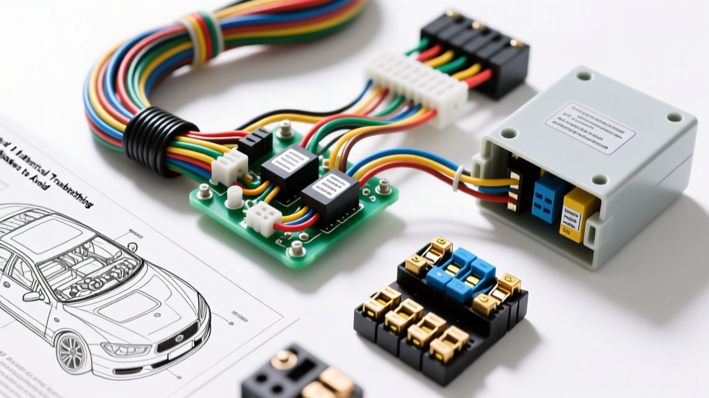
The High Stakes of Auto Electrical Troubleshooting
Modern vehicles are rolling networks of sensitive microprocessors, high-speed data buses, and high-current power distribution systems. When a fault occurs, the margin for error is razor-thin. Proper auto electrical troubleshooting requires more than just a basic understanding of Ohm's Law; it demands strict adherence to safety protocols and diagnostic methodologies. A single slip of a multimeter probe or the use of outdated testing tools can destroy a $2,000 Engine Control Module (ECM), trigger an unintended Supplemental Restraint System (SRS) deployment, or result in severe personal injury.
As automotive electrical systems evolve to include 48-volt mild-hybrid architectures and 400-volt+ full EV platforms, the consequences of diagnostic errors have multiplied. Below, we detail the most critical mistakes technicians and DIYers make during auto electrical troubleshooting, alongside the exact safety warnings and corrective protocols you must follow.
Mistake #1: Using Incandescent Test Lights on Solid-State Circuits
The traditional incandescent test light is a relic that has no place in modern module diagnostics. An incandescent bulb draws between 1.0 and 2.5 Amps of current to illuminate. While this is negligible for a 1970s headlight circuit, it is catastrophic for modern low-side driver circuits.
The Failure Mode
Many modern ECMs and Body Control Modules (BCMs) use low-side transistor drivers to control relays, solenoids, and LED lighting. These drivers are often rated for a maximum of 500mA to 1A. If you probe a 5-volt reference signal or an injector control wire with an incandescent test light, the sudden current draw will instantly overheat and short the internal driver transistor, permanently destroying the module. Furthermore, probing SRS (airbag) squib circuits with a test light can provide enough current to detonate the pyrotechnic charge, causing severe injury.
- Correction: Use a high-impedance Digital Multimeter (DMM) with a minimum 10-Megaohm input impedance.
- Alternative: Use an automotive-specific LED logic probe that draws less than 10mA, or a Fluke Automotive DMM equipped with a low-Z (impedance) mode to eliminate ghost voltages without drawing destructive current.
Mistake #2: Destructive Backprobing of Weather-Pack and Metri-Pack Connectors
To read live data at a sensor connector, technicians often "backprobe" the rear of the connector. The mistake lies in using oversized paperclips, thick test light probes, or improper terminal release tools to force past the silicone weather seals.
Terminal Fretting and Moisture Ingress
Standard Delphi Metri-Pack 150 and 280 series terminals rely on precise spring tension (measured in grams of retention force) to maintain a gas-tight connection. Forcing a thick probe into the rear of the connector spreads the terminal tines. When you remove the probe, the terminal no longer grips the mating pin tightly. This causes fretting corrosion—a micro-arcing phenomenon that generates aluminum oxide, increasing resistance and causing intermittent sensor dropouts. Worse, you compromise the silicone ribbed weather seal, allowing road salt and moisture to cause "green death" (copper oxide corrosion) inside the connector cavity.
- Correction: Use dedicated, ultra-thin backprobe pins (typically 0.4mm to 0.6mm diameter) specifically designed for the terminal series you are testing.
- Alternative: Use a breakout box or a dedicated harness jumper (pigtail) that mates perfectly with the OEM connector, allowing you to probe the exposed jumper wires safely.
Mistake #3: Relying on Continuity (Ohms) for High-Current Circuits
One of the most pervasive errors in auto electrical troubleshooting is using the Ohms (Ω) continuity function to verify the integrity of high-current power and ground cables, such as 10 AWG starter feeds or 8 AWG alternator B+ wires.
Why Continuity Lies
A standard DMM uses less than 1mA of current to measure resistance. A 12 AWG wire with only one strand of copper intact out of 19 total strands will show 0.5Ω of resistance on your meter. The meter will beep "continuity." However, when the starter solenoid demands 40 Amps, that single strand will act as a resistor, melt, and cause a no-crank condition. Continuity only tells you if a circuit is completely broken, not if it can carry its designed load.
The Voltage Drop Solution
Voltage drop testing measures the circuit's ability to do work under a live load. You must test the circuit while it is actively consuming current (e.g., cranking the engine or running the cooling fans).
| Circuit Type | Wire Gauge (Typical) | Max Allowable Voltage Drop | Testing Condition |
|---|---|---|---|
| Main Battery Cables (B+ / Ground) | 4 AWG - 1/0 AWG | 0.2V (Total Circuit) | Engine Cranking |
| Starter Control Circuit (S-Terminal) | 14 AWG - 16 AWG | 0.5V | Key in START Position |
| Alternator Output to Battery | 8 AWG - 4 AWG | 0.2V | Engine @ 2000 RPM, Loads ON |
| 5V Reference / Sensor Ground | 18 AWG - 20 AWG | 0.05V (50mV) | Key ON, Engine OFF (KOEO) |
Mistake #4: Piercing Wire Insulation with T-Pins
When a connector is sealed, buried, or inaccessible, the temptation to pierce the wire insulation with a sewing needle or T-pin to get a meter reading is high. This is a guaranteed way to create a future failure point.
The Corrosion Catalyst
Piercing the PVC or cross-linked polyethylene (XLPE) insulation exposes the bare copper to atmospheric oxygen and moisture. Within weeks, capillary action wicks moisture under the insulation jacket, corroding the copper strands far beyond the puncture site. This increases resistance and eventually causes the wire to snap under engine vibration.
- Correction: Never pierce wires. If a harness must be opened, use a solder-seal splice kit to repair the access point, or better yet, access the signal at the module connector or a designated diagnostic breakout port.
Mistake #5: Waking Modules During Parasitic Draw Testing
Diagnosing a dead battery requires a parasitic draw test. The classic mistake is pulling fuses one by one while watching an ammeter connected in series with the battery. This methodology is fundamentally flawed on any vehicle built after 1996 (OBD-II era).
The Sleep Cycle Disruption
Modern vehicles have dozens of modules that communicate over the CAN bus. When the ignition is turned off, these modules do not shut down instantly; they enter a "sleep" cycle that can take anywhere from 15 to 45 minutes. Pulling a fuse drops voltage to a module, which instantly wakes up the entire CAN network, resetting the sleep timer. Furthermore, pulling a fuse interrupts power to the radio or BCM, which may trigger anti-theft lockouts.
- Correction: Use a low-amp clamp meter (capable of measuring down to 1mA) around the negative battery cable. This allows you to monitor the current without breaking the circuit or dropping voltage to the modules. Wait the full 45 minutes for the vehicle to enter deep sleep before recording your baseline draw.
Mistake #6: Shorting the CAN Bus Network
The Controller Area Network (CAN bus) is the nervous system of the vehicle. According to the SAE J1939 Standard and ISO 11898, the CAN bus relies on a differential voltage signal between CAN-High (CAN-H) and CAN-Low (CAN-L).
OBD-II Pinout and Shorting Risks
At the standard OBD-II Data Link Connector (DLC), Pin 6 is typically CAN-H and Pin 14 is CAN-L. The terminating resistors at each end of the bus network are 120Ω each, creating a parallel resistance of 60Ω. When probing these pins, standard DMM leads are thick and the pins are closely spaced. Slipping with a probe can bridge Pin 6 and Pin 14.
- The Result: Shorting CAN-H and CAN-L instantly collapses the differential voltage. The network goes down, the vehicle may stall, and multiple "U-codes" (Network Communication codes) will be set in every module. In some poorly protected architectures, this can backfeed voltage into sensitive CAN transceivers.
- Correction: Always use alligator clips or dedicated DLC breakout boards with built-in test points for network diagnostics. Verify the 60Ω resistance with the battery disconnected before applying power.
Safety Warning: Hybrid and EV High-Voltage Isolation
As ASE Certification Guidelines for L3 (Light Duty Hybrid/Electric Vehicle) emphasize, auto electrical troubleshooting now frequently involves High Voltage (HV) systems ranging from 200V to 800V. These systems utilize bright orange cabling.
Lock-Out / Tag-Out (LOTO) Protocol
Never assume an EV or Hybrid is safe to work on simply because the ignition is off. The HV battery contactors may remain closed, or a fault may have welded them shut.
- Disconnect the 12V Auxiliary Battery: This removes the control voltage required to keep the HV contactors closed.
- Pull the Manual Service Disconnect (MSD): This physically breaks the HV battery pack in half, dropping the output voltage to zero.
- Verify Zero Voltage: Wait the manufacturer-specified time (usually 10-15 minutes) for the inverter capacitors to bleed off. Use a CAT III or CAT IV rated DMM to verify 0V at the inverter terminals before touching anything.
- Wear PPE: Always wear Class 0 (1000V rated) insulated rubber gloves with leather protectors when working near orange cabling.
Conclusion: Precision Over Speed
Effective auto electrical troubleshooting is a discipline of patience and precision. By abandoning destructive test lights, respecting terminal integrity, utilizing voltage drop over continuity, and strictly adhering to high-voltage safety protocols, you protect both yourself and the vehicle's intricate electronics. Invest in high-impedance meters, proper breakout boxes, and low-amp clamps—they will pay for themselves the first time they save an ECM from a preventable diagnostic error.