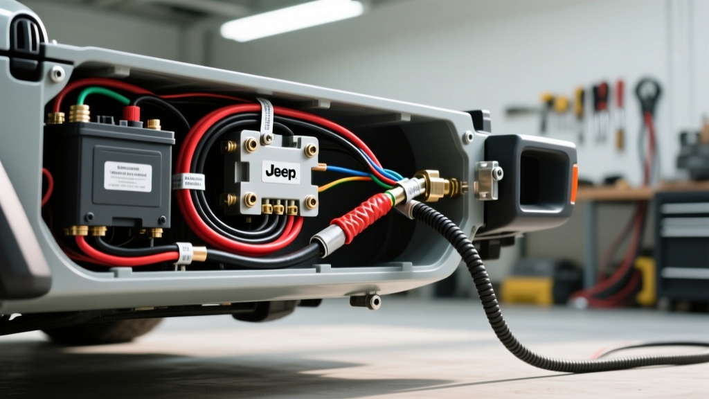
Diagnosing the Root Cause of Jeep Wrangler Electrical Problems
The 2007-2018 Jeep Wrangler (JK platform) is an iconic off-road vehicle, but it is notoriously plagued by chronic electrical gremlins. Owners frequently report stalling, random accessory failures, and fuel pump cut-outs. While many mechanics immediately blame sensors or the ECU, the true culprits behind the most common Jeep Wrangler electrical problems are inadequate factory wiring, dissimilar metal corrosion at ground points, and the flawed Totally Integrated Power Module (TIPM). To permanently resolve these issues, a systematic hardware and wiring upgrade is required.
The Factory Grounding Flaw
The JK Wrangler utilizes a braided aluminum ground strap connecting the engine block to the chassis. In off-road environments, this strap is exposed to water, mud, and road salt. Furthermore, the copper ring terminals mated to the aluminum block create a galvanic corrosion cell. Over time, resistance at the ground junction increases, causing severe voltage drops. When the engine control module (ECM) or fuel pump module experiences a ground-side voltage drop exceeding 0.1V, the vehicle will exhibit erratic shifting, misfires, or complete stalling.
TIPM Fuel Pump Relay Failure
The TIPM acts as the central nervous system for the Wrangler's power distribution. Unfortunately, the internal surface-mount solder joints for the fuel pump relay are subjected to high thermal cycling and current loads. These micro-fractures eventually cause the internal relay to fail, cutting power to the fuel pump. Because the TIPM is sealed and the internal relay is not officially serviceable, dealerships typically recommend replacing the entire $1,200+ module. However, a proper external relay bypass harness solves this specific Jeep Wrangler electrical problem for a fraction of the cost.
Required Materials and Wiring Specifications
Before beginning the installation, gather the following heavy-duty materials. Do not use cheap copper-clad aluminum (CCA) wire; always specify 100% oxygen-free copper (OFC) to handle the high amperage and thermal loads of the Pentastar V6 or 3.8L V6 engines.
| Component | Wire Gauge (AWG) | Wire Type / Color | Terminal / Connector | Torque Specification |
|---|---|---|---|---|
| Alternator B+ Cable | 1/0 AWG | Red OFC Welding Cable | 5/16" (8mm) Ring Terminal | 10 Nm (88 in-lbs) |
| Main Battery Positive | 1/0 AWG | Red OFC Welding Cable | 3/8" Ring / Side Post | 7 Nm (62 in-lbs) |
| Engine-to-Chassis Ground | 4 AWG | Black THHN / OFC | 5/16" Ring Terminal | 28 Nm (21 ft-lbs) |
| TIPM Bypass Load Circuit | 12 AWG | Red Primary Wire (GXL) | Spade / Butt Connectors | N/A (Crimp Only) |
| TIPM Bypass Trigger Circuit | 18 AWG | Red/Black Primary (GXL) | Add-A-Circuit / Spade | N/A (Crimp Only) |
Phase 1: Upgrading the Alternator Positive and Auxiliary Grounds
Upgrading the main power delivery and grounding infrastructure eliminates the voltage drops that confuse the Wrangler's CAN-bus system and TIPM logic boards.
Step 1: Alternator B+ Cable Replacement
The factory alternator positive cable is often undersized (typically 4 AWG) and routed near high-heat exhaust manifolds. Disconnect the negative battery terminal and wait 15 minutes for the TIPM capacitors to discharge.
- Remove the factory 8mm nut securing the B+ wire to the alternator output stud. Note: The Denso alternators on the 3.6L Pentastar use an 8mm stud, while some 3.8L models use a 10mm stud. Verify your hardware before crimping.
- Route the new 1/0 AWG red OFC cable away from the exhaust headers, utilizing factory wire loom and split-loom tubing.
- Secure the 5/16" ring terminal to the alternator B+ stud. Torque to exactly 10 Nm (88 in-lbs). Over-torquing will strip the brass nut or snap the alternator diode plate stud.
- Route the cable to the positive battery terminal, trim to length, and crimp the terminal using a hydraulic or heavy-duty ratcheting crimper.
Step 2: Engine-to-Chassis Auxiliary Ground
The factory braided strap is insufficient for modified Jeeps with high-draw accessories (winches, light bars, air compressors).
- Locate the passenger side engine lift bracket or a clean, unpainted casting point on the engine block.
- Use a wire wheel to remove all paint, powder coating, and corrosion down to bare metal.
- Attach a 4 AWG black OFC cable with a 5/16" ring terminal to the block. Torque the bolt to 28 Nm (21 ft-lbs).
- Route the cable to the inner fender chassis. Drill a 5/16" hole if a factory ground stud is unavailable. Clean the chassis contact point to bare steel, attach the terminal, and coat the entire junction with di-electric grease to prevent future galvanic corrosion.
Phase 2: Installing the External Fuel Pump Relay Bypass
To bypass the failing internal TIPM fuel pump relay, we will install a standard Bosch-style 5-pin automotive relay (using only 4 pins) triggered by the factory M25 fuel pump fuse circuit.
Bypass Wiring Pinout and Connections
- Pin 30 (Load In): Connect a 12 AWG red wire directly to the battery positive terminal. You MUST install a 20A inline MAXI fuse holder within 6 inches of the battery connection to protect the circuit.
- Pin 87 (Load Out): Run a 12 AWG red wire from Pin 87 to the factory fuel pump power wire. Locate the TIPM C3 connector (the grey connector). The fuel pump feed wire is typically Dark Green with a White tracer (Pin 19). Splice into this wire using a marine-grade adhesive-lined butt connector, or tap it at the fuel pump module access hatch under the rear seat for easier access.
- Pin 86 (Trigger In): Use an 18 AWG red wire connected to an 'Add-A-Circuit' fuse tap. Insert the tap into the M25 (20A) Fuel Pump fuse cavity in the TIPM. This ensures the external relay only activates when the ignition commands the fuel pump on.
- Pin 85 (Trigger Ground): Connect an 18 AWG black wire from Pin 85 to a clean, bare-metal chassis ground point near the TIPM.
Important Note: Once the external relay is installed and tested, remove the original M25 fuel pump fuse from the TIPM to prevent the internal failing relay from attempting to carry the load and potentially melting the TIPM circuit board.
Crimping and Termination Best Practices
The harsh environment under a Wrangler's hood demands military-grade termination. Never use solder on high-current automotive battery cables; solder wicks into the wire strands, creating a rigid point that will fatigue and snap under engine vibration. Instead, use a ratcheting crimper designed for the specific AWG size. After crimping, seal every connection using 3:1 shrink ratio marine-grade heat shrink tubing. The inner adhesive lining melts and flows into the wire strands, preventing capillary action from wicking moisture and causing internal copper oxidation.
Testing and Voltage Drop Validation
After completing the installation, you must validate the repairs using a digital multimeter (DMM) set to DC millivolts (mV). Voltage drop testing is the only scientifically accurate way to confirm the resolution of these Jeep Wrangler electrical problems.
- Positive Side Test: Place the red probe directly on the alternator B+ nut and the black probe directly on the positive battery post. Start the engine and turn on all accessories (headlights, blower motor on high). The DMM should read less than 100mV (0.1V).
- Ground Side Test: Place the red probe on the negative battery post and the black probe on the alternator casing (bare metal). Under load, the reading must be less than 50mV (0.05V).
- Fuel Pump Circuit Test: Back-probe the fuel pump connector at the tank. With the engine cranking or running, verify that the voltage matches the battery voltage within 0.2V, confirming the external TIPM bypass is delivering full system voltage without restriction.
Authoritative References
For further reading on automotive cable standards and diagnostic procedures, consult the following resources:
- SAE J1128: Low Tension Primary Cable Standards - Society of Automotive Engineers (Specifications for GXL and OFC wire insulation and current carrying capacity).
- Haynes Jeep Wrangler Repair Manual - Comprehensive wiring diagrams and TIPM connector pinouts for JK generation vehicles.
- National Highway Traffic Safety Administration (NHTSA) - Technical Service Bulletins (TSBs) regarding TIPM failures and fuel system electrical faults.