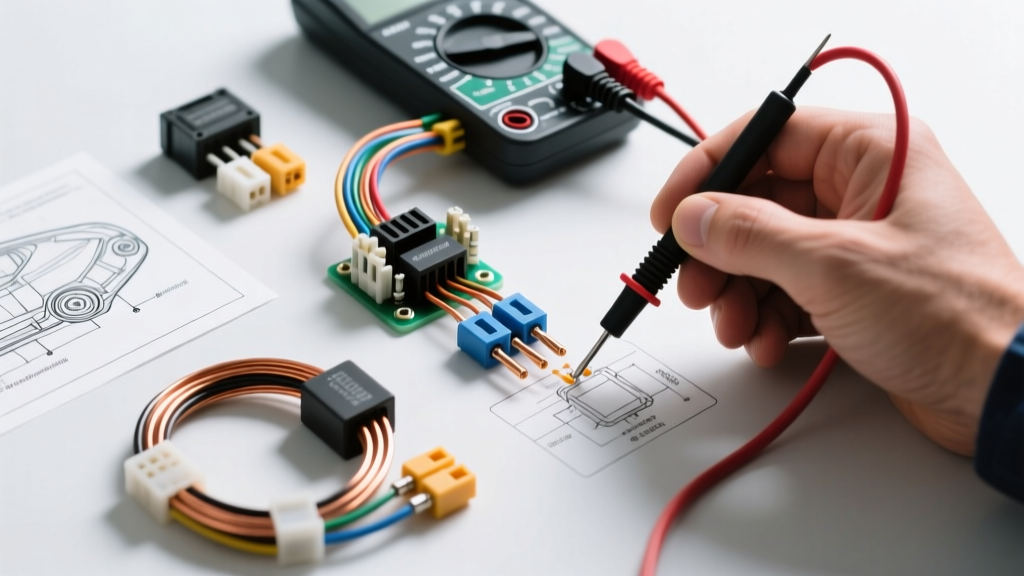
The Core Philosophy: Half-Splitting the Circuit
When diagnosing car electrical problems, the most common mistake technicians make is 'part swapping' based on guesswork. Professional automotive electricians rely on a logical process known as half-splitting. Instead of testing every component sequentially from the battery to the load, you measure the voltage or resistance at the exact midpoint of the circuit. If the midpoint has correct voltage, the fault lies in the second half (the ground side or the load). If the midpoint lacks voltage, the fault lies in the first half (the power supply or switches). This step-by-step troubleshooting flow eliminates 50% of the circuit with a single multimeter probe placement.
Phase 1: Visual and Baseline Verification
Before connecting a digital multimeter (DMM), establish a known-good baseline. A flawed baseline will corrupt every subsequent diagnostic step.
- Battery State of Charge (SOC): Measure resting voltage at the posts (not the cable clamps). A fully charged AGM battery should read 12.8V to 13.0V; a standard flooded lead-acid battery should read 12.6V.
- Terminal Integrity: Check for galvanic corrosion (white/green crust) under the insulation. Even if the clamp feels tight, copper oxide acts as a semiconductor, restricting high-amperage current flow.
- Ground Strap Verification: Inspect the main engine-to-chassis ground strap. On many GM and Ford trucks, this braided 4 AWG copper strap is prone to fraying and corrosion where it bolts to the cylinder head.
Phase 2: Starter Circuit Voltage Drop Decision Tree
Voltage drop testing is the definitive method for diagnosing car electrical problems related to high-current loads. It must be performed under load (while cranking the engine). Below is a diagnostic flow focused on the GM LS-based V8 starter circuit (found in Silverado, Tahoe, and Camaro platforms), utilizing the traditional 12 AWG Purple control wire and 4 AWG main battery feed.
Step-by-Step Starter Diagnostic Matrix
| Test Point (Under Cranking Load) | Expected DMM Reading (DC mV) | Failure Mode & Next Step |
|---|---|---|
| Battery (+) Post to Starter B+ Terminal | < 0.20V (200mV) | High Reading: Corroded 4 AWG red cable, loose battery clamp, or internal cable strand breakage. Inspect cable ends. |
| Starter Housing to Engine Block | < 0.10V (100mV) | High Reading: Paint, rust, or oil between starter mounting face and block. Clean mating surfaces to bare metal. |
| Engine Block to Chassis Ground Point | < 0.10V (100mV) | High Reading: Frayed braided ground strap. Replace with a minimum 4 AWG copper strap and apply dielectric grease to terminals. |
| IGN Relay Output to Starter Solenoid 'S' Pin | < 0.15V (150mV) | High Reading: High resistance in the 12 AWG Purple wire, corroded weather-pack connector, or failing ignition switch contacts. |
Expert Insight: If the voltage drop on the positive side is acceptable, but the starter still cranks slowly, move your DMM black lead to the battery negative post and the red lead to the starter housing. A reading above 100mV confirms a ground-side restriction, often caused by a corroded engine block ground bolt.
Phase 3: Tracking Parasitic Drains via Module Wake-Up
Modern vehicles feature complex CAN bus networks. A parasitic drain is rarely a simple 'light left on'; it is usually a module failing to enter sleep mode. Acceptable sleep current for a modern vehicle is typically below 50mA after a 20-minute timeout period.
Diagnosing CAN Bus Wake-Up Faults
When diagnosing car electrical problems involving parasitic drains, you must monitor the network topology. Connect your DMM to the OBD-II Data Link Connector (DLC) to monitor the Controller Area Network (CAN) bus lines.
- Pin 6 (CAN High): Should rest at roughly 2.6V during active communication and drop to near 0V in sleep mode.
- Pin 14 (CAN Low): Should rest at roughly 2.4V during active communication and rise to near 5V (or match CAN-H) in sleep mode.
The Termination Resistor Test
With the battery disconnected and the modules asleep, set your DMM to Ohms. Measure resistance between OBD-II Pin 6 and Pin 14. You should read exactly 60 Ohms. This is because the CAN bus requires two 120-Ohm termination resistors (one in the PCM, one in the BCM or ABS module) wired in parallel.
Decision Tree:
- Reading ~120 Ohms: One termination resistor is missing or a module has dropped off the bus. Check for an open circuit in the CAN wiring harness.
- Reading < 60 Ohms: A short to ground, a short between CAN-H and CAN-L, or an aftermarket device (like a cheap insurance dongle or alarm) is back-feeding the network and preventing sleep.
Phase 4: Sensor Reference Voltage (5V VREF) Diagnostics
A common scenario when diagnosing car electrical problems is encountering a vehicle that stalls, hesitates, or throws multiple seemingly unrelated sensor codes (e.g., MAP, TPS, and APP sensors simultaneously). These sensors share a 5-Volt Reference (VREF) circuit provided by the Powertrain Control Module (PCM).
Isolating a Shorted 5V VREF Circuit
If the PCM detects a short to ground on the 5V VREF line, it will often shut down the reference voltage entirely to protect its internal circuitry, causing all shared sensors to fail.
- Set DMM to DC Volts. Back-probe the 5V VREF wire at the Throttle Position Sensor (TPS). (On many Ford Ecoboost engines, this is a Brown/White wire; on GM LS engines, it is typically a Gray wire).
- Key ON, Engine OFF. If reading is 0V or erratic (e.g., 1.2V), suspect a short.
- Half-Split the Sensors: Unplug the sensors sharing the VREF circuit one by one. If unplugging the MAP sensor causes the voltage at the TPS to instantly snap back to 5.0V, the fault is an internal short inside the MAP sensor or a chafed wire in the MAP pigtail.
- Check the Wiring: If unplugging all sensors yields no change, the short is in the main engine harness. Look for areas where the harness rubs against the alternator bracket or cylinder head, melting the insulation and shorting the 5V reference to the engine block.
Authoritative References & Further Reading
To deepen your understanding of automotive electrical diagnostics, consult the following industry standards and technical resources:
- AA1Car: Voltage Drop Testing Guide - A comprehensive breakdown of acceptable voltage drop limits across various automotive circuits and connector types.
- SAE International: J1113 Electromagnetic Compatibility Standards - Essential reading for understanding how shielding, twisted-pair CAN bus wiring, and grounding strategies prevent electrical interference in modern vehicles.
- Helm Incorporated (OEM Service Manuals) - The official publisher for Ford, GM, and Honda factory service manuals, providing exact pinouts, wire color codes, and connector cavity maps necessary for precise half-splitting diagnostics.
Summary of Diagnostic Best Practices
Successfully diagnosing car electrical problems requires patience, a high-impedance digital multimeter, and strict adherence to logical testing flows. Never pierce wire insulation with test probes, as this introduces moisture and guarantees future corrosion. Always use proper back-probing pins or T-pin adapters at weather-pack connectors. By mastering voltage drop testing, understanding CAN bus sleep states, and systematically isolating shared reference circuits, you will resolve complex electrical faults that defeat trial-and-error mechanics.