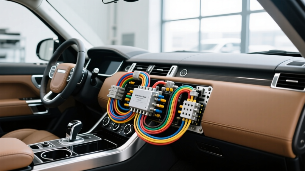
The Hidden Cost of Range Rover Upgrades
When embarking on an upgrade or modification project for a Range Rover L322 (2002-2012) or L405 (2013-2021), enthusiasts frequently encounter a wall of complex fault codes. Adding auxiliary lighting, winches, or dual-battery systems often triggers a cascade of Range Rover electrical problems that leave owners stranded or facing massive dealership diagnostic bills. Unlike older, simpler vehicles, modern Land Rovers utilize a highly sensitive multiplexed CAN-bus (Controller Area Network) and LIN-bus (Local Interconnect Network) architecture. The Body Control Module (BCM) and Central Junction Box (CJB) continuously monitor circuit resistance, voltage drops, and current draw. Any aftermarket modification that alters these parameters—even slightly—will be flagged as a fault, resulting in limp mode, air suspension failure, or parasitic battery drain.
Why Land Rover CAN-Bus Systems Reject Aftermarket Mods
The primary culprit behind post-modification Range Rover electrical problems is backfeed and Pulse Width Modulation (PWM) interference. Land Rover’s smart alternators do not output a steady 14.4V; they fluctuate between 12.2V and 15.0V based on battery state-of-charge and engine load, controlled via a single-wire LIN-bus connection to the Engine Control Module (ECM). If you wire a standard Voltage Sensitive Relay (VSR) or a cheap LED light bar directly into the factory harness, the PWM signals and voltage spikes will backfeed into the CAN-bus network. According to AA1CAR's CAN-bus diagnostic guidelines, introducing unshielded aftermarket wiring near the CAN-High and CAN-Low twisted pairs induces electromagnetic interference (EMI), corrupting data packets and throwing U-codes (e.g., U0401 - Invalid Data Received from ECM).
Diagnostic Decision Tree: Common Range Rover Electrical Problems
Use this symptom-cause-fix decision tree to isolate faults introduced during your modification project.
- Symptom: Dashboard lights up with ABS, HDC (Hill Descent Control), and Suspension faults immediately after installing an LED light bar.
Cause: The LED driver lacks CAN-bus decoding and is feeding PWM ripple back into the lighting circuit, which the BCM interprets as a short or bulb outage.
Fix: Install a CAN-bus opto-isolator relay harness. Do not tap the factory headlight wires directly. Use the factory high-beam trigger wire (typically Blue/White on L322) solely to switch an isolated 12V relay coil, powering the LEDs directly from the auxiliary battery. - Symptom: Auxiliary dual battery is perpetually dead; DC-DC charger or VSR never engages.
Cause: The Range Rover smart alternator drops voltage to 12.4V during coasting to reduce engine drag. A standard 13.3V VSR will disengage, and basic DC-DC chargers will fault out.
Fix: Bypass the VSR entirely. Install a smart 40A DC-DC charger (e.g., Redarc or Victron) with a dedicated D+ ignition sense wire connected to the OBD2 port Pin 1 (Ignition Switched) rather than relying on alternator voltage sensing. - Symptom: Vehicle battery dies overnight; air suspension drops completely.
Cause: An aftermarket accessory (like a dashcam or tracker) is keeping the CAN-bus "awake," preventing the BCM from entering sleep mode.
Fix: Perform a parasitic drain voltage drop test across the CJB fuses. The vehicle must draw less than 30mA after a 20-minute sleep cycle. Rewire the accessory to a true ignition-switched source, not a constant 12V "always on" circuit.
Proper Wiring Integration: Dual Battery & Aux Lighting Specs
To prevent Range Rover electrical problems, your physical wiring must meet or exceed OEM standards for vibration, moisture, and current capacity. The L322 and L405 engine bays run exceptionally hot, particularly near the supercharged V8 or turbo-diesel manifolds. All under-hood wiring must be routed in split-loom corrugated tubing and secured every 8 inches.
| Component / Circuit | Wire Gauge (AWG) | Protection & Fuse | Connector Type & Routing Notes |
|---|---|---|---|
| Main Battery Interconnect (Dual Battery) | 2 AWG (Welding Cable) | 150A MIDI Fuse (within 6" of source) | Adhesive-lined heat shrink ring terminals. Torque M8 battery nuts to 6 Nm. |
| Auxiliary LED Light Bar (40A-60A draw) | 8 AWG (Primary to Relay) | 60A Maxi Fuse | Deutsch DT 2-pin connectors at the grille. Route away from the LIN-bus alternator wire. |
| CAN-Bus Trigger / Opto-Isolator | 18 AWG (Stranded) | 5A Mini Blade Fuse | Solder and heat-shrink only. Never use T-taps on Land Rover CAN-H (Pin 6) or CAN-L (Pin 14). |
| Winch Solenoid Control Circuit | 10 AWG | 30A Circuit Breaker | Use IP67-rated weatherpack connectors. Route through the firewall via the blanking grommet behind the glovebox. |
Diagnosing Parasitic Drain from Aftermarket Gear
If your modification project results in a dead battery, do not simply disconnect the negative terminal to test current with a multimeter in series. Breaking the circuit resets the Range Rover’s BCM sleep timer, meaning you will have to wait another 20 to 45 minutes for the modules to power down, leading to false high-readings. Instead, use the Voltage Drop Method across the fuses in the Central Junction Box (CJB) and Rear Electronics Module (REM).
Set your digital multimeter to the millivolt (mV) range. Probe both sides of each fuse with the vehicle locked and asleep. Using Ohm’s law, a voltage drop across a known resistance (the fuse) indicates current flow. For example, a 10A mini-blade fuse has a resistance of roughly 0.0075 ohms. If you measure 0.75mV across it, you are drawing roughly 100mA—far above the 30mA threshold allowed by Land Rover specifications. If you find the offending circuit, trace it back to your aftermarket relay or DC-DC charger. Often, the issue is a solid-state relay that leaks 2-5mA of current, which compounds when multiple accessories are installed. Swap solid-state relays for heavy-duty mechanical Bosch-style relays with integrated flyback diodes to suppress inductive voltage spikes that can fry the BCM.
Securing Ground Points to Prevent Module Resets
A massive percentage of Range Rover electrical problems stem from poor aftermarket grounding. Land Rover uses pulse-width ground switching for many interior and exterior circuits. If you tie an aftermarket audio amplifier or winch contactor to a factory ground stud (typically an M6 or M8 bolt on the chassis or inner fender), the sudden high-amperage draw will cause a localized voltage drop. This ground offset tricks sensitive modules into thinking they have lost power, causing spontaneous reboots. Always fabricate a dedicated ground bus bar for aftermarket gear, bolted directly to bare, unpainted chassis metal using a star washer and an M8 stainless steel bolt, torqued to 12 Nm, and coated with dielectric grease to prevent galvanic corrosion.
References & Wiring Standards
For further technical data on multiplexed networks and heavy-duty wiring standards, consult the following resources:
- SAE International J1939 / CAN-Bus Standards - Essential for understanding data bus interference and twisted-pair shielding requirements.
- AA1CAR Parasitic Battery Drain Diagnostics - Comprehensive guide on voltage drop testing across automotive fuse panels without breaking the sleep circuit.