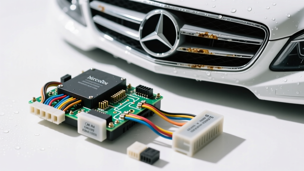
Understanding the Multiplexed Architecture of the E350
When addressing Mercedes Benz E350 electrical problems, technicians must abandon traditional point-to-point wiring logic. Spanning the W211 (2006-2009) and W212 (2010-2016) chassis, the E350 relies on a highly complex, multiplexed network governed by Signal Acquisition Modules (SAMs) and the Electronic Ignition Switch (EZS/EIS). The vehicle utilizes multiple Controller Area Network (CAN) buses—primarily CAN-C (Powertrain) and CAN-B (Chassis/Body)—to route data. Consequently, a single corroded pin or chafed wire can cascade into seemingly unrelated failures across the dashboard, transmission, and comfort systems.
Front SAM (N10/1): The Epicenter of Water Intrusion Failures
The Front Signal Acquisition Module (designated N10/1) is the primary gateway for the chassis CAN-B network and handles high-current power distribution for the wipers, lighting, and HVAC blower. In the W211 chassis, the Front SAM is located in the passenger front footwell kick panel. This location makes it highly susceptible to water intrusion.
The Clogged Sunroof Drain Pathway
The most frequent catalyst for Front SAM failure is the clogging of the front right sunroof drain tube or the HVAC evaporator condensation drain. When these drains obstruct, water bypasses the seals and pools directly in the passenger footwell, submerging the lower portion of the SAM enclosure. Because Terminal 30 (Constant Battery Power) is routed to the lower pins, 12V battery voltage inevitably bridges into the 5V CAN-B data lines via electrolytic corrosion.
Front SAM Pinout and Power Supply Verification
Before replacing a suspected faulty Front SAM, you must verify the integrity of the power supply and data lines. A voltage drop on the main power feed will cause the SAM's internal microprocessors to reset randomly, throwing erratic U-codes (Network Communication codes).
| Pin | Circuit Designation | Wire Color | AWG | Function | Expected Voltage / Value |
|---|---|---|---|---|---|
| 14 | Terminal 30 | Red/Green | 10 AWG | Constant Battery + | 12.2V - 12.6V (Max 0.2V Drop) |
| 35 | Terminal 15 | Black/Yellow | 14 AWG | Ignition On Power | 0V (Off) / 12.0V+ (On) |
| 22 | CAN-B High | Green | 20 AWG | Chassis CAN + | 2.6V (Idle) / 3.5V (Active) |
| 23 | CAN-B Low | Green/White | 20 AWG | Chassis CAN - | 2.4V (Idle) / 1.5V (Active) |
| 41 | Terminal 31 | Brown | 10 AWG | Chassis Ground | < 0.05V Drop to Batt Neg |
CAN-B Network Faults and Waveform Diagnostics
When water bridges Pin 14 (12V) and Pin 22 (CAN-B High), the 12V surge travels across the entire CAN-B network. This overvoltage condition triggers the protective transceivers in other modules (like the Rear SAM, Door Control Units, and the EZS) to shut down, effectively taking the chassis network offline. The classic symptom is a "Key Won't Turn" or "Steering Lock Defective" message, as the EZS cannot communicate with the Electronic Steering Lock (ESL) to verify the key fob.
Terminating Resistor and Ohmmeter Testing
To isolate a CAN-B network fault without immediately requiring an oscilloscope, utilize your Digital Multimeter (DMM) to check the network's terminating resistors. According to SAE J2284 CAN Standards, a healthy high-speed CAN network requires two 120-ohm terminating resistors in parallel, yielding a total resistance of 60 ohms.
- Disconnect the vehicle battery negative terminal to prevent module damage.
- Access the OBD-II diagnostic port. On W211/W212 models, CAN-B High is typically routed to Pin 3, and CAN-B Low to Pin 11.
- Set your DMM to Ohms (Ω) and measure between Pin 3 and Pin 11.
- Diagnostic Decision Tree:
- Reading ~60Ω: Network wiring and terminating resistors (located inside the Front SAM and EZS) are intact. Suspect a module transceiver failure.
- Reading ~120Ω: One terminating resistor is missing or an open circuit exists in the CAN wiring harness.
- Reading <40Ω or 0Ω: A hard short exists between CAN-H and CAN-L, or a module has suffered internal water damage, shorting the data lines to ground or power.
Alternator LIN Bus Communication Failures
Another prevalent issue among Mercedes Benz E350 electrical problems involves the charging system. The E350 does not use a traditional voltage sense wire for the alternator. Instead, the Engine Control Module (ME-SFI) commands the alternator's voltage regulator via a Local Interconnect Network (LIN) bus. The LIN wire is typically Green/Violet (20 AWG).
This wire routes from the engine harness, down past the alternator bracket, and into the regulator connector. Vibration and heat cause the insulation to chafe against the aluminum alternator bracket. When the LIN bus shorts to ground, the ME-SFI loses communication with the alternator. The failsafe default is to output a static 13.5V, regardless of battery state-of-charge or electrical load, eventually triggering a "Battery Not Charging" warning on the instrument cluster. Always perform a voltage drop test on the LIN bus wire with the engine running; a flat 0V or static 12V reading (instead of a 7-10V PWM square wave) confirms a broken or shorted LIN circuit.
Parasitic Draw: Rear SAM and Quiescent Current Sleep Modes
The W212 E350 moved the Rear SAM (N10/2) to the trunk area, where it controls the fuel pump, rear lighting, and rear HVAC actuators. Failed trunk weatherstripping or tail light gaskets allow water to wick into the Rear SAM connector, causing severe parasitic battery drains.
Step-by-Step Quiescent Current Measurement
Diagnosing a parasitic draw on a multiplexed Mercedes requires patience. The CAN buses do not go to sleep immediately upon turning off the ignition. Modules remain active for up to 45 minutes as they write data to non-volatile memory and perform self-tests. For advanced diagnostic methodologies regarding module sleep states, refer to the International Automotive Technicians Network (iATN) technical bulletins on European quiescent current testing.
- Prepare the Bypass Circuit: Never connect an ammeter directly in series with the battery without a bypass switch. Connecting the DMM after the modules have gone to sleep will introduce a voltage drop that wakes the CAN bus back up, ruining the test. Wire a heavy-duty toggle switch in parallel with your DMM's 10A amperage clamps.
- Initial Connection: With the bypass switch CLOSED (allowing current to bypass the DMM), disconnect the negative battery terminal and connect your test setup.
- Induce Sleep Mode: Close all doors, latch the hood and trunk strikers manually, and lock the vehicle with the remote. Wait a minimum of 45 to 60 minutes.
- Measure Quiescent Current: Slowly OPEN the bypass switch, forcing all current to flow through the DMM. A healthy W212 E350 should drop to below 30mA (0.03A).
- Isolate the Fault: If the draw remains high (e.g., 400mA+), begin pulling fuses associated with the CAN-B network and the Rear SAM (N10/2) in the trunk. A sudden drop in current when pulling the Rear SAM fuse confirms water intrusion or an internal short within the module.
Summary of Best Practices
Resolving complex Mercedes Benz E350 electrical problems requires a systematic understanding of network topology. Always inspect the physical environment of the SAM modules for moisture before condemning the electronics. Utilize Picoscope or high-end DMMs to verify CAN bus differential voltages, and respect the vehicle's quiescent sleep timers when diagnosing parasitic draws. By focusing on the data lines and power distribution nodes outlined above, you can accurately diagnose and repair the most stubborn electrical faults in the W211 and W212 platforms.