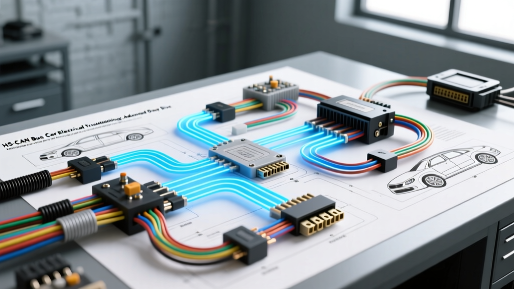
Introduction to Advanced Multiplexed Network Diagnostics
Modern vehicles have largely abandoned discrete, point-to-point 12V wiring in favor of multiplexed communication networks. When performing advanced car electrical troubleshooting on late-model platforms, technicians must shift their mindset from simple continuity testing to high-speed signal analysis. The High-Speed Controller Area Network (HS-CAN), governed by ISO 11898-2, serves as the primary backbone for critical powertrain and chassis modules. Because these networks operate using differential voltage signaling rather than simple 12V DC pulses, traditional digital multimeter (DMM) testing often yields misleading results. True diagnostic mastery requires an understanding of network topology, precise voltage drop thresholds, and module sleep-state management.
The Limitations of Basic Multimeter Testing
A standard DMM samples voltage at a rate of roughly 2 to 4 times per second. HS-CAN bus signals toggle between dominant and recessive states at up to 500 kilobits per second (kbps). Consequently, a multimeter will only display an 'average' voltage—typically around 2.5V to 2.7V on CAN-High and 2.3V to 2.5V on CAN-Low. While these averages can indicate a gross short to power or ground, they are entirely useless for identifying intermittent signal degradation, termination resistor faults, or twisted-pair impedance mismatches. Advanced diagnostics mandate the use of a digital storage oscilloscope (DSO) paired with targeted voltage drop testing.
HS-CAN Topology and OBD-II DLC Pinout Specifications
The HS-CAN bus utilizes a twisted-pair unshielded cable to minimize electromagnetic interference (EMI). The twist rate is critical, typically specified at one twist per inch (approx. 25mm). Wire gauge is predominantly 20 AWG (0.5mm²) or 22 AWG (0.35mm²) copper. The network relies on a linear bus topology with two 120-ohm termination resistors located at the extreme ends of the backbone (usually inside the Engine Control Module and the Transmission Control Module or Body Control Module). When measured in parallel, a healthy HS-CAN backbone should exhibit 60 ohms (± 2 ohms) of resistance between CAN-High and CAN-Low with the battery disconnected.
| Pin | Signal Name | Wire Gauge (Typical) | Color Code (Varies by OEM) | Function & Voltage Specs |
|---|---|---|---|---|
| 6 | CAN-High (HS) | 20 AWG (0.5mm²) | White, Orange/White, or Dark Green | Differential High: Recessive 2.5V / Dominant 3.5V |
| 14 | CAN-Low (HS) | 20 AWG (0.5mm²) | Blue, Orange/Brown, or Dark Green/White | Differential Low: Recessive 2.5V / Dominant 1.5V |
| 4 | Chassis Ground | 16 AWG (1.5mm²) | Black | Low-impedance path to vehicle chassis |
| 5 | Signal Ground | 18 AWG (0.8mm²) | Black/Pink or Black/White | Clean logic ground reference for ECM/PCM |
Advanced Car Electrical Troubleshooting: Voltage Drop on Data Lines
While voltage drop testing is traditionally associated with heavy-gauge power and ground circuits (e.g., starter motors or alternators), it is equally vital for data lines. Resistance in a CAN bus circuit alters the differential voltage, leading to bit errors and module communication DTCs (such as U0100 - Lost Communication with ECM). The maximum allowable voltage drop across any splice, connector, or length of 20 AWG data wire is strictly 0.1V under active network load.
Step-by-Step Voltage Drop Testing Protocol
- Step 1: Connect your DMM positive lead to the CAN-High wire at the OBD-II DLC (Pin 6).
- Step 2: Connect your DMM negative lead to the CAN-High wire at the target module connector (e.g., ECM Pin 12).
- Step 3: Turn the ignition ON (engine off) to wake the network. Do not crank the engine, as EMI from the starter will skew readings.
- Step 4: Read the DC voltage drop. A reading of 0.02V to 0.05V is normal. Anything exceeding 0.1V indicates high resistance.
- Step 5: Repeat the process for CAN-Low (DLC Pin 14 to ECM Pin 13).
High resistance on data lines is rarely caused by broken wires; it is almost always the result of fretting corrosion inside the connector cavities. Micro-vibrations cause the tin or silver plating on 1.2mm or 1.5mm female terminals to oxidize. When repairing these terminals, never use standard dielectric grease, which is an insulator. Instead, apply a conductive contact grease such as NYOGEL 760G to the terminal mating surfaces to displace moisture and restore conductivity.
Parasitic Drain Diagnosis on Multiplexed Networks
Parasitic battery drain is one of the most complex facets of modern car electrical troubleshooting. Modules connected to the CAN and LIN (Local Interconnect Network) buses must enter a 'sleep' state after the ignition is turned off and the doors are locked. Sleep state current draw should drop below 30mA (typically 15mA - 25mA) within 20 to 45 minutes. If a single module fails to sleep, or if a short on a LIN bus keeps the master module polling, the draw can exceed 400mA, killing the battery overnight.
The Shunt Method: Avoiding Module Wake-Up
The most common mistake technicians make is pulling fuses or disconnecting the battery terminal to insert an ammeter. Breaking the circuit interrupts power, forcing every module on the network to reboot and stay awake for another 30 minutes. To accurately measure parasitic draw, you must use a shunt bypass method:
- Connect a heavy-gauge jumper wire across the negative battery terminal and the disconnected negative cable.
- Set your DMM to the 10A setting and connect the probes in parallel with the jumper wire.
- Remove the jumper wire. The current now flows through the DMM shunt without ever interrupting the vehicle's electrical continuity.
- Lock the vehicle and monitor the current drop over 45 minutes using the DMM's MIN/MAX recording feature or an oscilloscope with a low-amp current clamp (e.g., Fluke i410).
| Symptom / Draw Profile | Probable Root Cause | Advanced Diagnostic Fix |
|---|---|---|
| Steady 450mA draw, no sleep transition after 60 mins. | Short to ground on a LIN bus slave circuit keeping the BCM awake. | Isolate LIN wire (usually 22 AWG Purple/White). If draw drops, test slave nodes (HVAC, Rain Sensor) for internal shorts. |
| Draw drops to 20mA, then spikes to 300mA every 4 minutes. | Telematics or GPS module attempting to ping a cellular network due to poor antenna connection. | Check antenna coaxial cable impedance (should be 50 ohms). Inspect roof-mounted shark fin antenna for water ingress. |
| U0140 (Lost Comm with BCM), CAN-H reads 0.0V, CAN-L reads 2.5V. | CAN-High shorted to chassis ground between Splice Pack and BCM. | Perform pinpoint voltage drop test on CAN-H. Locate chafed harness near the kick panel or A-pillar. Repair using solder-seal splices. |
Oscilloscope Waveform Analysis and Repair Standards
When a DMM indicates a network fault, an oscilloscope is required to visualize the differential signal. A healthy HS-CAN waveform will show CAN-High stepping up to 3.5V and CAN-Low stepping down to 1.5V simultaneously during a dominant bit state, returning to a mutual 2.5V during recessive states. The differential voltage (CAN-H minus CAN-L) must be exactly 0V in recessive and 2.0V in dominant.
Identifying Real-World Failure Modes via Waveforms
- Open Circuit on CAN-Low: CAN-High will operate normally (2.5V to 3.5V), but CAN-Low will flatline at 2.5V or float erratically. The network may default to single-wire mode, reducing baud rate and causing intermittent DTCs.
- Short Between CAN-H and CAN-L: Both channels will overlay perfectly on the scope, showing identical voltage fluctuations. Differential voltage remains at 0V. Total network failure occurs.
- Missing Termination Resistor: The waveform will exhibit severe 'ringing' or voltage overshoot at the edges of the square waves due to signal reflection. Measured backbone resistance will read 120 ohms instead of 60 ohms.
OEM Wiring Repair Standards
When repairing HS-CAN twisted pair wiring, standard crimp connectors are strictly prohibited. They alter the twist rate and introduce impedance mismatches that cause signal reflection. According to ISO 11898-1 physical layer specifications, the twist rate must be maintained up to the repair point. Repairs must be performed using adhesive-lined heat shrink solder sleeves (e.g., Raychem RT-1145). The solder seal ensures a permanent metallurgical bond, while the internal thermoplastic adhesive creates a waterproof barrier against capillary action and corrosion. For comprehensive diagnostic test modes and OBD-II compliance standards, technicians should refer to the SAE J1979 documentation. Utilizing these advanced methodologies transforms guesswork into precise, repeatable car electrical troubleshooting. For further reading on precision measurement tools, the Fluke Automotive Voltage Drop Guide provides excellent supplementary visual references for DMM setup and safety protocols.