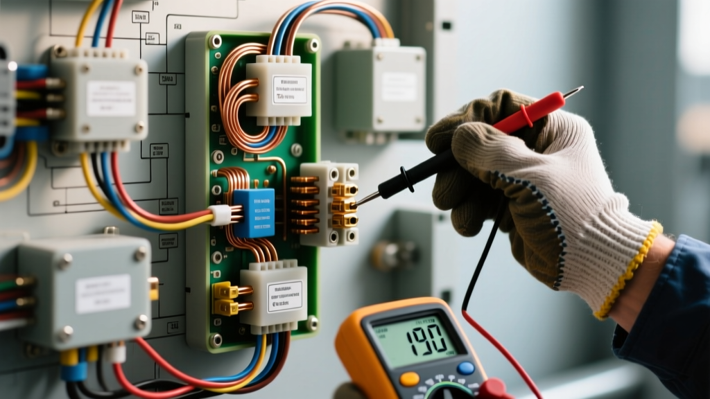
Why Generic Multimeters Fail Modern CAN-Bus Diagnostics
When attempting to repair car electrical problems on late-model vehicles, technicians often make the critical mistake of using generic hardware store digital multimeters (DMMs). Modern Controller Area Network (CAN) bus systems and sensitive Engine Control Module (ECM) 5-volt reference circuits require a DMM with a strict 10-megohm (10MΩ) input impedance. Using a meter with lower impedance creates a parallel resistance path, artificially loading the circuit and pulling down the voltage. This leads to false diagnoses, such as replacing a perfectly good Throttle Position Sensor (TPS) when the meter itself caused the voltage drop.
Furthermore, automotive environments demand CAT III or CAT IV safety ratings to safely test high-voltage hybrid and EV systems without risking arc flash injuries. To systematically isolate faults, your diagnostic toolkit must be curated specifically for the harsh, high-frequency environment of modern vehicle networks.
Essential Meter Specifications to Repair Car Electrical Problems
To effectively isolate faults, your diagnostic toolkit must include specific measurement capabilities beyond basic DC voltage and continuity. According to AutoShop 101 Electrical Fundamentals, understanding circuit loading and signal frequency is paramount.
- Min/Max Recording: Intermittent wiring faults, such as a chafed harness rubbing against a firewall, only register for milliseconds. A Min/Max feature captures voltage dropouts that the human eye cannot see on a standard LCD refresh rate.
- Duty Cycle and Frequency (Hz): Critical for testing Pulse Width Modulated (PWM) signals, such as fuel injector pulses, variable valve timing (VVT) solenoids, and cooling fan control modules.
- Millisecond (ms) Pulse Width: Necessary for measuring the exact on-time of fuel injectors. A typical idle pulse width on a port-injected 5.3L V8 is between 2.5ms and 3.5ms.
- True RMS: Essential for accurately reading non-linear AC waveforms generated by alternators and hybrid motor-generators.
Product Comparison: Top DMMs for Automotive Diagnostics
| Model | Impedance | Min/Max | Best Application | Price Tier |
|---|---|---|---|---|
| Fluke 88 V Automotive | 10MΩ | Yes (1ms capture) | CAN-Bus, PWM, Fuel Injectors | Premium ($400+) |
| Power Probe IV | Variable | No | Power/Ground feeding, Relay testing | Mid ($250) |
| INNOVA 5610 | 10MΩ | Yes | General sensor testing, Alternator ripple | Budget ($150) |
| Fluke 87V Industrial | 10MΩ | Yes | Heavy duty, EV High Voltage (CAT IV) | Premium ($450+) |
Note: While the Power Probe IV is exceptional for forcing power and ground to actuators, it should never be used to back-probe ECM sensor circuits, as its internal resistance can damage sensitive driver transistors.
Specialized Wiring Tools for Pinpoint Fault Isolation
Back-Probes and Terminal Sizing
Piercing wire insulation with a T-pin or sewing needle is a cardinal sin in automotive electrical repair. It exposes copper strands to moisture, guaranteeing future corrosion and green crust (copper oxide) buildup. Instead, use dedicated automotive back-probes matched to the terminal cavity size. Proper back-probing ensures you are reading the exact voltage at the male-to-female terminal interface without spreading the female tangs.
- 0.64mm Probes: Used for micro-terminals found in modern airbag modules, camera systems, and ECM sensor inputs (typically 22-24 AWG wire).
- 1.5mm Probes: The standard for most Deutsch connectors, weather-pack seals, and general sensor harnesses (18-20 AWG wire).
- 2.8mm to 4.8mm Probes: Reserved for high-current circuits like fuel pump feeds, starter solenoids, and relay outputs (12-14 AWG wire).
Low-Amp Clamps for Parasitic Draws
Standard multimeter 10A ports are useless for modern parasitic drain diagnosis because they require breaking the circuit and can blow internal fuses if a module wakes up. You need a dedicated low-amp inductive clamp (like the Fluke i410 or equivalent) capable of resolving down to 0.1mA. Modern vehicles require a sleep current between 20mA and 50mA. If your clamp only resolves to 10mA, you will completely miss a faulty Bluetooth module drawing an extra 15mA and killing the battery over three days.
Breakout Boxes for Transmission and ABS Modules
When diagnosing internal transmission solenoid faults (such as the Ford 6R80 or GM 8L90), back-probing the transmission harness connector can spread the delicate female terminals, causing future intermittent connection issues. A dedicated transmission breakout box allows you to disconnect the harness, plug the breakout box inline, and measure the resistance (typically 2.0 to 6.0 ohms at 68°F) and PWM duty cycle safely without risking terminal damage.
Real-World Application: Diagnosing a Shorted 5V Reference
Let us apply these tools to a common scenario: a 2012 Chevrolet Silverado 5.3L cranking but failing to start, with a U0100 code and no communication with the ECM. According to Fluke Automotive CAN-Bus Testing Guidelines, network dropouts require systematic isolation.
- Verify DLC Power: Connect your 10MΩ DMM to the OBD2 Data Link Connector. Pin 16 should read battery voltage (12.6V), and Pins 4 and 5 must show clean chassis and battery grounds (less than 0.05V drop under load).
- Check CAN-Bus Integrity: Switch to Min/Max DC voltage. Probe Pin 6 (CAN-High) and Pin 14 (CAN-Low). With the key on, CAN-H should idle around 2.6V and CAN-L around 2.4V. If both read 0V or 12V, you have a short to ground or power.
- Isolate the 5V Reference: On GM LS platforms, the 5V reference is often a Gray wire shared by the MAP, TPS, and APP sensors. If this Gray wire shorts to ground, the ECM protects itself by shutting down internally, killing the CAN bus. Use your DMM to back-probe the 5V pin at the ECM X2 connector. If it reads 0.00V, unplug sensors one by one until the 5V reference pops back to 5.00V, identifying the internally shorted component.
Voltage Drop Testing High-Current Starter Circuits
When repairing car electrical problems related to slow cranking, never rely on a static battery voltage test. A battery can show 12.6V at rest but drop to 6V under a 200-amp starter load due to internal sulfation or high-resistance battery cables (typically 4 AWG or 2 AWG).
Set your DMM to DC Volts and place the red lead on the battery positive post and the black lead on the starter B+ terminal. Crank the engine. The voltage drop across the entire positive side must not exceed 0.2V. Next, test the ground side: red lead on the starter case (clean metal), black lead on the battery negative post. The drop must not exceed 0.1V. If the ground drop is high, inspect the engine-to-chassis braided ground strap. When replacing ground studs on GM trucks, ensure the mating surface is stripped to bare metal and torqued to exactly 9 Nm (80 in-lbs) to prevent micro-arcing.
Summary of OBD2 DLC Pinouts for Network Diagnostics
| Pin | Function | Expected Voltage (Key On) |
|---|---|---|
| 4 | Chassis Ground | 0.00V (Less than 0.05V drop) |
| 5 | Battery Ground | 0.00V (Less than 0.05V drop) |
| 6 | CAN-High (ISO 15765) | 2.6V - 3.5V |
| 14 | CAN-Low (ISO 15765) | 1.5V - 2.4V |
| 16 | Battery Positive (Hot) | 12.0V - 14.5V |
Mastering the use of high-impedance multimeters, proper back-probes, and low-amp inductive clamps is the only reliable way to repair car electrical problems on modern vehicles. Adhering to SAE network standards and utilizing the correct diagnostic methodology will save hours of misdiagnosis and prevent unnecessary parts replacement.