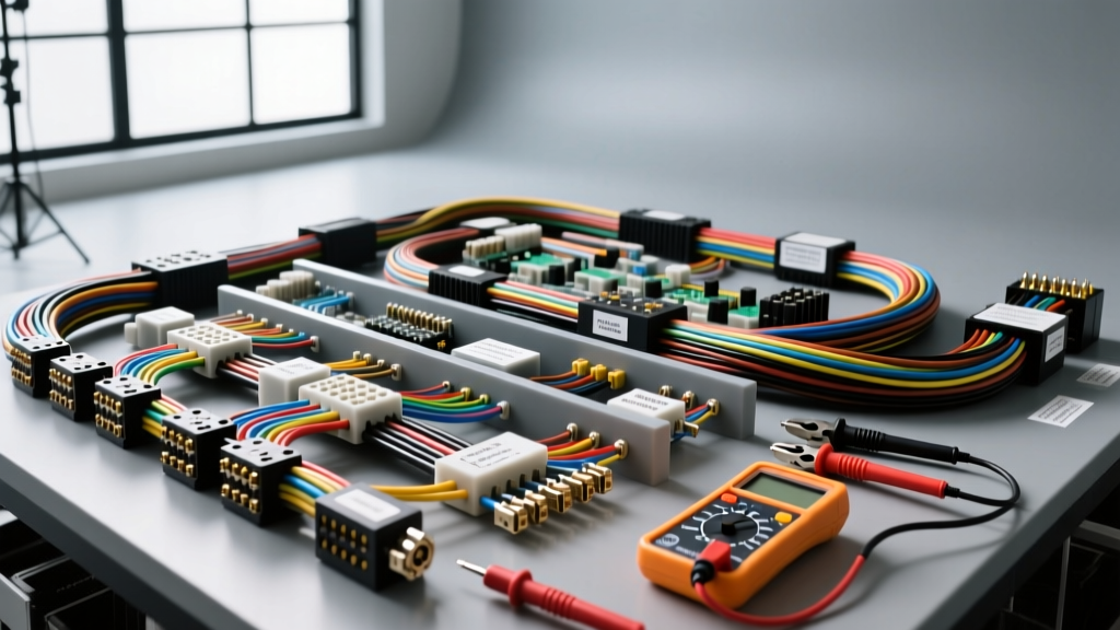
Technical Specifications for Car Electrical Diagnostic Tools
When diagnosing modern multiplexed networks, high-voltage EV architectures, and sensitive 5V powertrain control module (PCM) references, generic hardware store testers are insufficient. Professional car electrical diagnostic tools must meet stringent electrical specifications to prevent circuit loading, ensure accurate waveform capture, and protect the technician from transient voltage spikes. This technical reference outlines the exact specifications required for digital multimeters (DMMs), automotive oscilloscopes, and current clamps, alongside practical application data for OBD-II CAN-bus diagnostics and voltage drop testing.
1. Digital Multimeter (DMM) Impedance and Category Ratings
The most critical specification for any automotive DMM is input impedance. Modern engine management systems utilize 5V reference circuits for sensors like the Manifold Absolute Pressure (MAP) sensor and Throttle Position Sensor (TPS). These circuits are designed to supply a maximum of 100mA to 200mA. If a DMM with low impedance (e.g., 1MΩ or an incandescent test light) is connected, it will draw excessive current, pulling the 5V reference down to 2V or lower, and potentially triggering false PCM diagnostic trouble codes (DTCs) or damaging the internal driver transistor.
Professional automotive DMMs must feature a fixed input impedance of 10 Megohms (10MΩ). Furthermore, due to the high-energy transients generated by alternator load dumps and ignition coil primary circuits, the tool must carry a CAT III 1000V or CAT IV 600V safety rating. As detailed in Fluke's multimeter safety rating guidelines, CAT III/IV ratings ensure the internal arc-gap spacing and high-energy fuses (typically 11A/1000V HRC ceramic) can survive catastrophic voltage spikes without exploding.
| Circuit Type | Required DMM Impedance | Measurement Mode | Acceptable Tolerance |
|---|---|---|---|
| 5V PCM Reference (MAP, TPS) | 10MΩ Minimum | DC Volts (Auto-ranging) | ± 0.5% of reading |
| 12V B+ Power Feeds (Starter, Alt) | 10MΩ or Low-Z (LoZ) | DC Volts / Min-Max | ± 1.0% of reading |
| CAN-H / CAN-L Network | 10MΩ (Do not use LoZ) | DC Volts (Average) | ± 2.0% of reading |
| Injector Primary / Ignition Coil | 10MΩ | Duty Cycle / Dwell | ± 0.1 ms |
2. Oscilloscope Bandwidth and Sample Rate Requirements
While a DMM provides averaged DC voltage, an automotive oscilloscope captures rapid voltage transitions over time. For decoding high-speed Controller Area Network (CAN) buses, which operate at 500 kbps, or FlexRay networks operating at 10 Mbps, the scope's bandwidth and sample rate are paramount. A minimum bandwidth of 100 MHz and a real-time sample rate of 1 Gigasample per second (1 GS/s) are required to accurately resolve the rising and falling edges of digital square waves without aliasing.
According to Pico Technology's automotive diagnostics library, capturing a CAN-FD (Flexible Data rate) signal requires a scope capable of triggering on specific serial data patterns. Furthermore, test leads for oscilloscopes must be low-capacitance (typically under 100 pF/meter) to prevent the lead itself from acting as an antenna or altering the characteristic impedance of high-frequency communication buses.
Application Guide: OBD-II CAN-Bus Network Diagnostics
The physical layer of the OBD-II CAN-bus network is strictly governed by SAE J1962 standards. When diagnosing communication faults (e.g., U0100 Lost Communication with ECM), technicians must verify the physical wiring parameters at the Data Link Connector (DLC).
Wire Colors, AWG, and Pin Configurations
- Pin 6 (CAN High): Typically Yellow or Green/Yellow. 20 AWG to 22 AWG twisted pair.
- Pin 14 (CAN Low): Typically Brown or Yellow/Brown. 20 AWG to 22 AWG twisted pair.
- Pin 4 (Chassis Ground): 18 AWG or 16 AWG, connected to vehicle body ground.
- Pin 5 (Signal Ground): 18 AWG, dedicated PCM/Sensor ground reference.
- Pin 16 (Battery Positive): 16 AWG or 14 AWG, fused directly to B+ (hot at all times).
The CAN-H and CAN-L wires must be twisted at a rate of approximately 1 twist per inch to reject electromagnetic interference (EMI). The network relies on two 120-ohm terminating resistors located at the opposing ends of the bus (usually inside the PCM and the instrument cluster or ABS module). When measured with a DMM set to Ohms across Pin 6 and Pin 14 (with the battery disconnected), the parallel resistance must read exactly 60 ohms. A reading of 120 ohms indicates one open terminator, while a reading near 0 ohms indicates a short-to-ground or short-to-power.
CAN-Bus Voltage Bias Specifications
When the network is idle (recessive state), both CAN-H and CAN-L sit at a bias voltage of 2.5V. During active transmission (dominant state), CAN-H rises to approximately 3.5V, and CAN-L drops to approximately 1.5V. Using a DMM in Min/Max mode will capture these fluctuations, but an oscilloscope is required to measure the differential voltage and identify noise spikes caused by poor splice connections or chafed 22 AWG wiring harnesses.
Parasitic Draw Testing: Current Clamp Specifications
Modern vehicles feature complex sleep-cycle architectures. Modules like the telematics unit, body control module (BCM), and keyless entry receivers may take up to 45 minutes to enter a low-power sleep state. To diagnose a parasitic drain without breaking the circuit (which can wake modules back up), a Hall-effect AC/DC current clamp is mandatory.
Hall-Effect Clamp Technical Parameters
- Resolution: Minimum 1mA resolution (0.001A) for measuring sleep-state draws (typically 20mA to 50mA).
- Jaw Aperture: Small jaw (10mm to 13mm) to allow clamping around individual 10 AWG or 8 AWG fuse-circuit wires in the under-hood fuse block.
- Drift Rate: Must have a zero-drift rate of less than 0.5mA per hour to maintain accuracy during long-term sleep-cycle monitoring.
Diagnostic Sequence:
- Connect a 10 AWG jumper wire with a fuse in parallel with the negative battery terminal to prevent modules from resetting when the clamp is attached.
- Clamp the Hall-effect sensor around the negative battery cable. Ensure the wire is perfectly centered in the jaw aperture to avoid magnetic flux leakage errors.
- Zero the clamp using the physical null button on the tool.
- Close all doors, latch the hood switch, and lock the vehicle. Monitor the current over 45 minutes. A draw exceeding 50mA after all modules have slept indicates a faulty module, a stuck relay, or a shorted diode in the alternator.
Voltage Drop Testing and Connector Preservation
Voltage drop testing is the only accurate method for locating high-resistance faults in high-amperage circuits, such as 4 AWG starter feeds or 10 AWG fuel pump power supplies. According to Ohm's Law, resistance in a conductor generates heat and drops voltage. A healthy 12V starter circuit should exhibit no more than 0.2V drop across the entire positive cable and 0.1V drop across the ground path during engine cranking.
When back-probing connectors, tool selection is critical. Never use piercing probes or 'ice-pick' test leads on 20 AWG or 22 AWG communication wires. Piercing the insulation alters the wire's capacitance, causing signal reflection errors on CAN-bus networks, and introduces a pathway for copper oxidation (green rot). Instead, use specialized T-pin back-probes designed specifically for Delphi Weather-Pack, TE Connectivity AMP, and Bosch Motronic connectors. These probes slide past the rubber weather-seal and make contact with the male/female terminal mating surface without spreading the terminal tangs or compromising the IP67 waterproof seal.