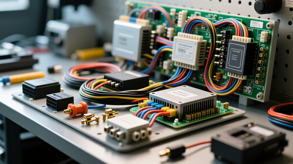
The Hidden Price Tag of Aftermarket Modifications
When planning a vehicle build, enthusiasts rarely ask how much do electrical problems in cars cost until a botched auxiliary light bar installation fries a $1,500 Body Control Module (BCM) or an undersized audio amplifier wire melts a firewall bulkhead connector. Upgrading your vehicle with high-draw accessories like 12,000-lb winches, 2000W Class D amplifiers, or PWM-driven LED rock lights introduces massive electrical loads that OEM wiring harnesses were never designed to handle.
According to SAE J1292 Automotive Electrical Systems standards, aftermarket circuits must be treated as independent systems with dedicated overcurrent protection and proper voltage drop management. Failing to do so results in catastrophic failure modes. This guide breaks down the real-world costs of modification-induced electrical faults and provides expert-level troubleshooting decision trees to diagnose and fix them before they destroy your vehicle's CAN bus network.
Cost Breakdown: Dealership vs. Auto Electrician Diagnostics
Understanding the financial impact of poor wiring practices is crucial for any modification project. Dealerships often flat-rate diagnostic times based on OEM troubleshooting trees, which fall apart when they encounter spliced aftermarket wires. Here is what you can expect to pay when botched upgrades cause system-wide failures:
| Fault Type | Root Cause (Aftermarket Mod) | Estimated Repair Cost | Time to Diagnose |
|---|---|---|---|
| BCM / ECM Failure | Backfeed from PWM headlight tap (LED Light Bar) | $1,200 - $3,500 (Part + Flash) | 2.5 - 4.0 Hours |
| CAN Bus U-Codes (U0140) | Scotch-Loks piercing CAN-H / CAN-L shielding | $300 - $600 (Harness Repair) | 1.5 - 3.0 Hours |
| Alternator Diode Bridge Melt | High-draw audio amp without Big 3 upgrade | $450 - $900 (Alternator Replace) | 1.0 Hour |
| Parasitic Battery Drain | Amplifier remote turn-on wired to constant 12V | $150 - $250 (Trace & Reroute) | 1.0 - 2.0 Hours |
Decision Tree: Troubleshooting Mod-Induced Electrical Faults
Use this symptom-cause-fix decision tree to isolate electrical gremlins introduced during your upgrade project.
Symptom 1: Headlights Flicker or Strobe When Bass Hits or Winch Engages
- Cause: Undersized ground wire or high-resistance chassis ground point causing voltage to seek an alternative path through the lighting circuit.
- Diagnostic Step: Set your Digital Multimeter (DMM) to DC Volts. Place the red probe on the alternator B+ terminal and the black probe on the amplifier/winch ground ring terminal under load. A reading above 0.2V indicates excessive ground resistance.
- Fix: Upgrade the ground path using 4 AWG OFC (Oxygen-Free Copper) wire. Scrape away all paint and clear coat at the chassis grounding point, use a stainless steel star washer to bite into bare metal, and coat the connection in dielectric grease to prevent galvanic corrosion.
Symptom 2: OBD2 Scanner Shows U0140 (Lost Communication with BCM) After Installing LED Rock Lights
- Cause: The installer tapped into the headlight or taillight circuit using a piercing splice connector. Modern vehicles use Pulse Width Modulation (PWM) to control lighting. Tapping a standard ISO relay coil directly to a PWM wire causes the relay to chatter, overheat, and send inductive voltage spikes back into the BCM driver transistor.
- Diagnostic Step: Inspect the headlight harness for blue or red Scotch-Lok connectors. Use an oscilloscope to check for square-wave PWM signals on the tapped wire.
- Fix: Remove all piercing splices. Solder and heat-shrink the OEM wire. Use an Add-A-Circuit fuse tap on a non-data, switched 12V fuse (e.g., wipers or 12V accessory socket) to trigger an isolated relay for the LED lights. Reference Mad Electrical's wiring guides for proper relay isolation techniques.
Technical Reference: Proper Upgrade Wiring & Fusing Specifications
Sizing your wire and overcurrent protection correctly is the single most important step in any electrical modification. Undersized wire causes voltage drop and heat; oversized fuses defeat the purpose of circuit protection. Always use SAE-rated stranded copper wire, never CCA (Copper-Clad Aluminum).
| Max Circuit Draw | Minimum Wire Gauge (AWG) | Recommended Fuse Type | Max Wire Length (12V System) |
|---|---|---|---|
| 10 Amps | 16 AWG | Mini / Micro2 | 10 Feet |
| 20 Amps | 12 AWG | ATO / Micro3 | 12 Feet |
| 30 Amps | 10 AWG | ATO / Bosch Relay | 15 Feet |
| 60 Amps | 6 AWG | MAXI | 15 Feet |
| 120 Amps | 2 AWG | MIDI / AMG | 10 Feet |
| 200+ Amps | 1/0 AWG | ANL / Class T | 8 Feet |
Note: Fuses must always be installed within 18 inches of the power source (battery or distribution block) to protect the entire length of the B+ wire. Consult the Littelfuse Automotive Fuse Technical Guide for time-current characteristics and interrupting ratings.
Step-by-Step: Diagnosing Voltage Drop in High-Draw Circuits
If your 12,000-lb winch is pulling 350 amps but the motor is bogging down, or your amplifier is clipping at half volume, you have a voltage drop issue. Voltage drop is the measurement of electrical potential lost as current pushes through resistance in the wire, terminals, and relays.
- Prep the DMM: Set your multimeter to DC Millivolts (mV) for high-resolution readings.
- Test the B+ Side: Place the red probe directly on the battery positive post and the black probe on the load side of your aftermarket relay (Pin 87). Engage the load (e.g., turn on the winch or hit the bass). A reading over 200mV (0.2V) means your positive cable, fuse holder, or relay contacts are degraded or undersized.
- Test the Ground Side: Move the red probe to the load's ground terminal and the black probe to the battery negative post. Engage the load. Again, anything over 200mV indicates a poor ground connection or undersized ground wire.
- Inspect Relay Pinouts: Ensure you are using a heavy-duty ISO Mini relay rated for 40A continuous. Standard pinouts are: Pin 30 (B+ from Battery), Pin 87 (Output to Load), Pin 86 (Switched 12V Trigger), and Pin 85 (Chassis Ground). Never run high-draw loads through the switch itself; always use the switch to trigger Pin 86.
Resolving Parasitic Drains from CAN Bus and Audio Accessories
A common aftermath of an audio or lighting upgrade is a dead battery after the vehicle sits for 48 hours. Modern vehicles feature complex CAN bus networks that can take up to 45 minutes to enter 'sleep mode' after the ignition is turned off. If an aftermarket device keeps a module awake, the parasitic drain will kill a Group 34 AGM battery in days.
The Parasitic Draw Test Protocol
- Disconnect the negative battery terminal and connect your DMM (set to 10A DC) in series between the negative post and the disconnected cable.
- Close all doors, remove the key, and latch the hood striker with a screwdriver so the vehicle thinks it is closed.
- Wait 45 to 60 minutes. Do not touch the vehicle or unlock it with the fob. You must allow the OEM modules to go to sleep.
- Read the DMM. A healthy, unmodified vehicle should read between 20mA and 50mA (0.02A - 0.05A).
- If the reading is 300mA or higher, begin pulling aftermarket fuses one by one. When the amperage drops back to the 50mA baseline, you have found the offending circuit.
Common Culprits and Fixes
- Amplifier Remote Turn-On (Blue Wire): Often incorrectly wired to a constant 12V source or a data-bus interface that never sleeps. Reroute the remote wire to a true ignition-switched 12V source or use a PAC TR-4 trigger module that senses B+ voltage changes to turn the amp on and off.
- Aftermarket Alarm / GPS Trackers: Cheap GPS modules wired directly to the battery without low-voltage cutoffs will drain the battery to 9V, causing BCM memory loss. Always wire these through an auxiliary fused distribution block with a low-voltage disconnect (LVD) relay.
By treating your aftermarket upgrades as integrated electrical systems rather than simple bolt-on accessories, you eliminate the hidden costs of electrical diagnostics and protect your vehicle's sensitive OEM computers from catastrophic failure.