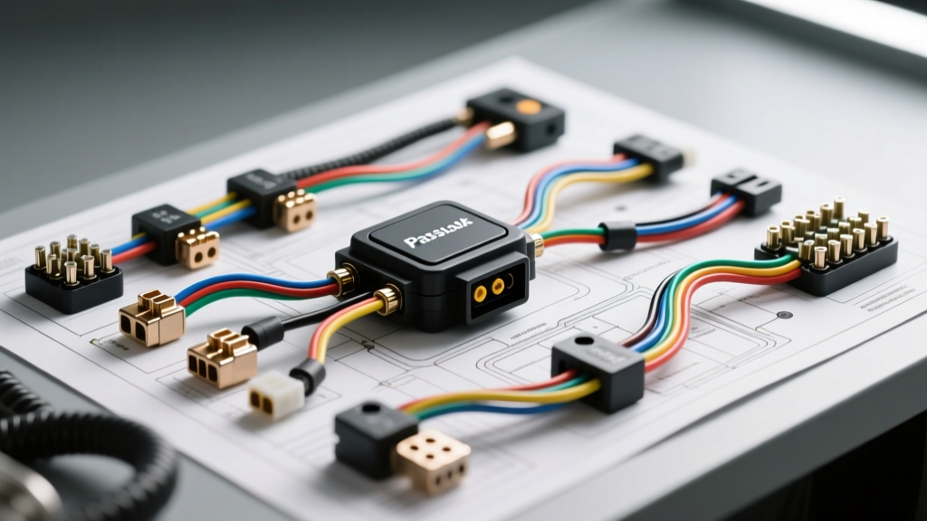
The Hidden Dangers of Immobilizer Wiring
When drivers and DIY mechanics encounter ignition interlock electrical problems, the immediate symptom is usually a no-crank or crank-no-start condition accompanied by a flashing security light. Modern vehicle anti-theft systems—such as GM's Passlock, Ford's PATS, and Chrysler's SKIS—rely on low-voltage logic circuits, RF transceivers, and precise resistance measurements to authorize engine starting. Unfortunately, the steering column is one of the most hazardous and complex wiring environments in the vehicle. Attempting to diagnose or bypass an ignition interlock without understanding the underlying electrical architecture frequently leads to catastrophic module failure, deployed airbags, or permanent harness damage. This guide outlines the critical safety warnings and common diagnostic mistakes that turn a simple security fault into a multi-thousand-dollar electrical nightmare.
Critical Safety Warnings: Airbags and PCM Vulnerability
Before inserting a multimeter probe into any steering column connector, you must recognize the physical and electrical hazards present in the interlock circuit environment.
1. The SRS (Airbag) Proximity Hazard
The ignition lock cylinder is physically mounted inches away from the Supplemental Inflatable Restraint (SIR) system components, including the clock spring and steering wheel airbag module. SRS wiring is universally identified by yellow conduit and yellow connector housings. Puncturing a yellow wire with a test probe or inadvertently shorting a 12V source to the SIR deployment circuit can cause an explosive airbag deployment. According to the NHTSA Airbag Safety Guidelines, technicians must always disconnect the negative battery terminal and wait a minimum of 15 minutes for the backup capacitors in the Sensing and Diagnostic Module (SDM) to discharge before working near the steering column.
2. PCM and BCM Logic Circuit Fragility
Ignition interlock sensors do not carry high-amperage starter current; they transmit 5-volt reference signals or low-amperage data pulses to the Powertrain Control Module (PCM) or Body Control Module (BCM). These internal module drivers are typically rated for a maximum of 50 to 100 milliamps. Applying external voltage or drawing excessive current during testing will instantly burn out the internal silicon traces of the PCM, requiring a complete module replacement and dealership reprogramming.
Top 3 Fatal Mistakes Causing Ignition Interlock Electrical Problems
Mistake 1: Using Incandescent Test Lights on 5V Logic Circuits
The most common mistake made when diagnosing a no-start security issue is using a standard incandescent test light to check for 'power' at the interlock sensor. A standard automotive test light draws between 0.5 and 2.0 amps to illuminate the bulb. When you connect this across a 5-volt reference wire or a low-amperage data line, you are forcing the PCM's internal 5V voltage regulator to supply far more current than it was designed to handle. This results in immediate thermal failure of the PCM driver. Rule: Never use a test light or a standard low-impedance solenoid tester on any immobilizer circuit. Always use a high-impedance Digital Multimeter (DMM) with a minimum input impedance of 10 Megohms.
Mistake 2: Piercing Wire Insulation on 22 AWG Signal Harnesses
To check the signal wire from the Passlock sensor, many DIYers use 'Scotch-locks', T-taps, or simply force a needle through the wire insulation. Interlock signal wires are typically 20 to 22 AWG (American Wire Gauge). Piercing the insulation exposes the bare copper to ambient moisture and road salt, initiating galvanic corrosion. Because the PCM measures the exact voltage drop across an internal resistor in the lock cylinder (often looking for a highly specific value like 2.43V), even 0.5 ohms of added resistance from corrosion at the puncture site will alter the voltage signal. The PCM will interpret this altered signal as an incorrect key, triggering an interlock fault and disabling the starter relay.
Mistake 3: Misdiagnosing the Starter Enable Relay Control Side
Many assume the ignition interlock system physically interrupts the heavy-gauge battery cable running to the starter solenoid. In 95% of modern vehicles, the interlock system simply prevents the PCM from grounding the control coil of the Starter Enable Relay. If the security system is active, the PCM leaves Pin 85 (or the equivalent control pin) open. Mechanics often waste hours testing the heavy 10 AWG battery feed circuits at the starter, completely missing the fact that the 18 AWG ground control wire at the relay is simply being held open by the PCM's theft-deterrent logic.
Technical Reference: GM Passlock II and Ford PATS Pinouts
Understanding the exact pinout and wire gauge is mandatory for safe backprobing and voltage drop testing. Below are the specifications for two of the most common interlock architectures.
| System / Component | Pin / Terminal | Wire Color | AWG Size | Function & Specifications |
|---|---|---|---|---|
| GM Passlock II Sensor | Pin A | Orange or White | 22 AWG | 5V Reference from BCM/PCM. Must read exactly 4.8V - 5.1V KOEO. |
| GM Passlock II Sensor | Pin B | Yellow | 22 AWG | Analog Signal to PCM. Voltage varies by key resistor pellet (e.g., 2.4V). |
| GM Passlock II Sensor | Pin C | Black | 20 AWG | Low Reference (Ground). Must have less than 0.05V drop to battery negative. |
| Ford PATS Transceiver | Pin 1 | White/Red | 18 AWG | 12V Ignition Feed (Run/Start). Protected by a 10A fuse in the CJB. |
| Ford PATS Transceiver | Pin 2 | Black/Yellow | 18 AWG | Chassis Ground. Critical for RF ring antenna resonance. |
| Ford PATS Transceiver | Pin 3 & 4 | Gray/Orange & White/Yellow | 22 AWG | TX and RX Data Lines. Twisted pair to reject EMI from wiper motors. |
For comprehensive connector cavity identification and terminal retention specs, technicians should consult the Aptiv (formerly Delphi) Connection Systems Catalog, which details the Metri-Pack 150 and 280 series terminals commonly used in these steering column harnesses.
Proper Backprobing and Voltage Drop Protocol
To diagnose ignition interlock electrical problems without damaging the 22 AWG wires or spreading the female terminal contacts, you must use dedicated terminal backprobe pins. Never use a paperclip or a standard test lead probe, as these will permanently spread the female terminal grips inside the Delphi connector, leading to intermittent open circuits caused by steering column vibration.
- Verify the 5V Reference: Backprobe Pin A (Orange/White) at the Passlock sensor connector. Turn the key to the ON position (KOEO). Your DMM should read between 4.9V and 5.1V. If it reads 0V, check for an open circuit or a short to ground in the harness. If it reads 12V, the harness has shorted to a battery-positive source, and the PCM internal driver is likely destroyed.
- Measure the Signal Voltage: Backprobe Pin B (Yellow). With the key OFF, it should read near 0V. Slowly turn the key to the ON position. The voltage should rise and stabilize at the specific resistance value coded for your key (usually between 1.5V and 3.5V). If the voltage fluctuates wildly as you turn the key, the magnet inside the lock cylinder is misaligned, or the hall-effect sensor is failing.
- Perform a Ground Side Voltage Drop: Place your DMM's red lead on Pin C (Black) at the sensor, and the black lead directly on the vehicle's battery negative post. Turn the key ON. A reading higher than 0.10V indicates excessive resistance in the ground circuit, which will skew the signal voltage and trigger a theft-deterrent fault.
Parasitic Drain and Security Module Sleep States
Another frequent issue tied to ignition interlock electrical problems is parasitic battery drain. Aftermarket bypass modules or poorly executed DIY relay bypasses often keep the PCM or BCM awake. Modern security modules utilize a 'sleep state' protocol, drawing less than 15 milliamps after the vehicle's data buses (CAN/GMLAN) go dormant. If an interlock bypass wire is spliced into a switched 12V ignition circuit but left tied to a constant 12V memory feed, the BCM will continuously poll the ignition lock cylinder, preventing the module from sleeping. This results in a 150mA to 300mA parasitic draw, killing the battery overnight. Always verify that any diagnostic jumper or bypass circuit is removed, and perform a 45-minute parasitic draw test using an inline ammeter to ensure the security modules have successfully entered their dormant state.
Authoritative References
- SAE J1930: Electrical/Electronic Systems Diagnostic Terms, Definitions, Abbreviations, and Acronyms - Essential for standardizing immobilizer and PCM fault terminology.
- NHTSA Airbag Safety Guidelines - Mandatory safety protocols for working in the steering column SIR environment.
- Aptiv Connection Systems - Reference for Metri-Pack terminal extraction and backprobing specifications.