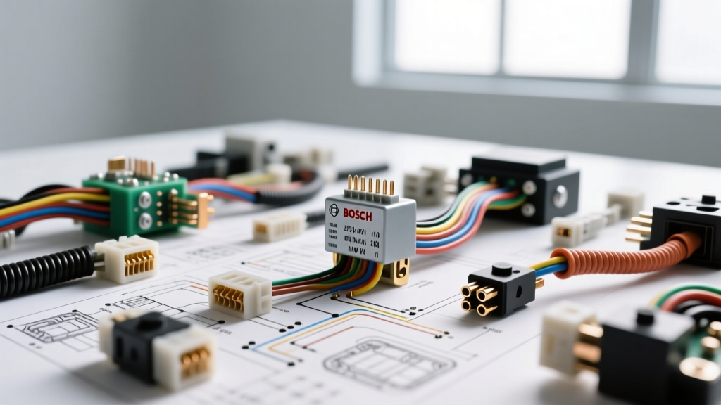
Mastering Automotive Electrical Wiring Problems and Solutions
When integrating aftermarket accessories like high-draw LED light bars, electric winches, or auxiliary fuel pumps, the relay harness is the critical intersection of control and power. However, this is also where most electrical wiring problems and solutions originate. A poorly constructed harness can lead to severe voltage drops, melted spade terminals, and catastrophic ECU backfeed. This practical installation and troubleshooting guide focuses on the industry-standard Bosch-style 5-pin ISO relay, providing actionable diagnostics, professional-grade installation protocols, and validation testing to ensure bulletproof circuit integrity.
The Anatomy of a Bosch-Style 5-Pin Relay
Before diagnosing faults, you must understand the internal architecture of the standard 5-pin micro ISO relay. The pinout is standardized across the automotive industry:
- Pin 30 (12V+ IN): The high-current power feed directly from the battery. Typically wired with 10 AWG or 12 AWG red wire.
- Pin 87 (12V+ OUT): The normally open (NO) high-current output to the load. Wired with 10 AWG or 12 AWG blue or white wire.
- Pin 87a (NC): The normally closed output. Rarely used in standard aftermarket lighting or winch installs.
- Pin 85 (Coil Ground): The ground path for the internal electromagnetic coil. Wired with 18 AWG black wire.
- Pin 86 (Coil Trigger): The low-current 12V+ switch signal from the cabin or ECU. Wired with 18 AWG yellow wire.
The internal coil typically exhibits a resistance of 70 to 90 ohms. When 12V is applied across pins 86 and 85, the coil energizes, pulling the internal contactor away from 87a and bridging pins 30 and 87. Understanding this mechanical action is the first step in resolving complex electrical wiring problems and solutions.
Symptom-Cause-Fix Diagnostic Matrix
Use the following decision tree to rapidly isolate faults in your relay harness. This matrix addresses the most frequent failure modes encountered in the field.
| Symptom | Root Cause | Targeted Solution |
|---|---|---|
| Relay Chatter (Rapid Clicking) | Voltage drop on the trigger circuit (Pin 86) preventing full coil saturation. | Upgrade trigger wire gauge; check for corrosion at the switch contacts; verify clean chassis ground for Pin 85. |
| Load Underperforming (Dim LEDs) | High resistance at Pin 30 or 87 spade terminals; undersized main power wire. | Perform voltage drop test; replace cheap stamped spade terminals with heavy-duty nickel-plated crimps; upgrade to 10 AWG. |
| ECU Damage / Blown Trigger Fuse | Inductive voltage spike (back-EMF) from the collapsing relay coil magnetic field. | Solder a 1N4001 flyback diode across pins 85 and 86 (cathode stripe facing Pin 86). |
| Relay Overheating / Melting Socket | Exceeding the relay's continuous amperage rating (usually 30A-40A max). | Calculate actual load draw; if exceeding 30A continuous, upgrade to a high-amperage solenoid or parallel dual relays. |
Deep Dive: Resolving Inductive Backfeed
One of the most destructive electrical wiring problems occurs when a solid-state switch or ECU driver controls the relay coil (Pin 86). When the trigger signal is removed, the magnetic field in the relay coil collapses, generating a high-voltage reverse spike (often exceeding 100V). This back-EMF can instantly fry a delicate MOSFET inside an ECU or a low-amperage solid-state switch.
The Solution: Install a flyback suppression diode. A standard 1N4001 rectifier diode is ideal. Solder the diode directly across the relay harness plug between Pin 85 and Pin 86. Critical Installation Note: The silver cathode stripe on the diode must point toward Pin 86 (the 12V+ trigger side). This allows normal current flow during operation but provides a recirculation path for the inductive spike when the circuit opens. According to diagnostic protocols outlined by AutoShop 101's electrical training resources, suppressing inductive spikes is mandatory when interfacing with modern CAN-bus systems or sensitive logic controllers.
Practical Installation Guide: Building a Bulletproof Harness
To prevent future faults, abandon cheap, pre-loomed gas-station relay kits. Build your harness using automotive-grade materials and SAE J1128 standards for low-tension primary cable.
Step 1: Wire Selection and Sizing
Always use cross-linked polyethylene (XLPE) insulated wire, such as GXL or TXL. These wires withstand high under-hood temperatures and resist abrasion far better than standard PVC wire. Refer to this sizing chart for 12V DC circuits (keeping voltage drop under 3%):
| Wire Gauge (AWG) | Max Continuous Amps | Application |
|---|---|---|
| 18 AWG | 6A - 8A | Coil Trigger (Pins 85, 86) |
| 14 AWG | 15A - 18A | Light Loads (Interior LEDs, small horns) |
| 12 AWG | 20A - 25A | Standard Lighting (55W Halogen bulbs) |
| 10 AWG | 30A - 40A | Main Relay Feed (Pin 30 to Battery) |
Step 2: Professional Crimping and Termination
The majority of electrical wiring problems and solutions revolve around poor terminations. Never rely on solder alone in high-vibration automotive environments; solder wicks into the wire strands, creating a rigid point that will eventually fatigue and snap. Instead, use open-barrel crimp terminals with a dedicated ratcheting crimper (such as those designed for Delphi Weather-Pack or Bosch OEM connectors). After crimping, seal the connection using adhesive-lined dual-wall heat shrink (e.g., 3M MDT) to prevent moisture ingress and capillary corrosion.
Step 3: Harness Routing and Looming
Route the harness away from exhaust manifolds, steering shafts, and sharp sheet metal. Use split-loom tubing for general protection, but switch to woven nylon expandable sleeving or Tesa tape in high-heat areas near the engine block. Secure the loom every 8 to 12 inches using UV-resistant zip ties or aluminum P-clips with rubber cushions. When passing through the firewall, always use a dedicated rubber grommet and apply dielectric grease to the wire bundle to prevent the grommet from tearing the wire insulation over time.
Validation: Performing a Voltage Drop Test
Once the installation is complete, do not simply turn the system on and assume it is working. You must validate the circuit integrity using a digital multimeter (DMM) set to DC Volts. As detailed in Haynes diagnostic tutorials, a voltage drop test is the only accurate way to measure dynamic circuit resistance under load.
The Testing Protocol:
- Prepare the Circuit: Turn on the accessory so current is actively flowing through the relay and wires.
- Test the Positive Side: Place your multimeter's red probe directly on the battery positive terminal. Place the black probe on the load's positive input terminal (after the relay). The DMM will display the voltage lost across the entire positive path (fuse, wiring, Pin 30, internal contactor, Pin 87, and connectors).
- Test the Negative Side: Place the red probe on the load's ground terminal and the black probe directly on the battery negative terminal.
- Evaluate the Results: A healthy automotive circuit should exhibit a total voltage drop of less than 0.5V (combined positive and negative sides). No single connection or terminal should drop more than 0.1V. If your DMM reads 0.8V or higher on the positive side, you have excessive resistance—likely due to a loose crimp, corroded spade terminal, or undersized wire.
Conclusion
Systematically addressing electrical wiring problems and solutions requires moving beyond simple continuity checks and embracing dynamic testing methodologies. By understanding the electromagnetic mechanics of the Bosch 5-pin relay, utilizing SAE-spec GXL wiring, implementing flyback diode protection, and validating your work with rigorous voltage drop testing, you transform a fragile aftermarket accessory into a permanent, reliable automotive system.