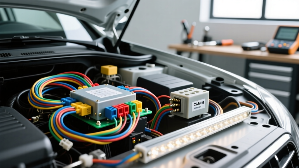
The Anatomy of a Post-Mod Electrical Issue with Car Networks
Upgrading to aftermarket LED light bars or auxiliary off-road lighting is a staple modification for trucks and SUVs. However, tapping into the OEM headlight circuit on modern platforms (like the Ram 1500, Ford F-150, or Chevy Silverado) frequently triggers a perplexing electrical issue with car warning on the dash, accompanied by relay chatter or hyper-flashing. This guide breaks down the systematic troubleshooting required to resolve CAN-bus and PWM (Pulse Width Modulation) conflicts introduced by high-draw or low-draw lighting modifications.
When you install a 50-inch LED light bar using a standard relay harness, you are interfacing with a highly sensitive Body Control Module (BCM). The BCM expects to see the electrical resistance of a 55W halogen H11 bulb (drawing approximately 4.5 Amps). An LED pod or light bar relay coil draws less than 0.2 Amps, while the LED bar itself draws varying amperage directly from the battery. According to Hella TechWorld documentation on CAN-bus systems, modern BCMs monitor the cold and warm resistance of lighting circuits. When the BCM detects an unexpected resistance delta, it logs a fault and triggers a generic electrical issue with car warning on the driver information display.
Furthermore, modern trucks do not send a steady 12V+ signal to the headlight circuit. They utilize a 500Hz to 2kHz PWM square wave to extend bulb life and run Daytime Running Lights (DRLs) at a 60% duty cycle. A standard Bosch-style 12V 40A relay coil cannot react fast enough to this pulsing signal, causing the relay to oscillate (chatter), melting the 85/86 coil pins and creating an intermittent short.
Symptom-to-Cause Diagnostic Matrix
Before tearing into your harness, use a True-RMS digital multimeter (DMM) to categorize your specific modification fault. Reference the matrix below to pinpoint the root cause of your electrical issue with car systems.
| Symptom | Multimeter / O-Scope Reading | Root Cause | Modification Fix |
|---|---|---|---|
| Relay Chatter / Flickering Lights | 6.5V RMS / 500Hz AC on trigger wire | PWM signal triggering a standard DC relay coil | Install PWM Anti-Flicker Decoder / Capacitor Bank |
| Dash "Bulb Out" or Generic Fault Warning | 1.2A Draw (Steady DC) on headlight circuit | BCM expects 4.5A halogen load, detects low draw | Add CAN-bus load resistor (10W 6-Ohm) in parallel |
| Intermittent Light Bar Cutout Under Load | 0.8V Voltage Drop across ground circuit | High resistance ground or undersized wire gauge | Upgrade to 10 AWG ground, use M6 ring terminal |
| TCM / ABS Dash Warnings After Splicing | 60-Ohm or Open Circuit on CAN lines | Spliced into CAN-Bus data lines, ruining termination | Remove splice, repair OEM harness, use isolated trigger |
Step-by-Step Diagnostic Procedure
1. Verifying the PWM Trigger Signal
Many modders assume a wiring fault when their new LED relay harness clicks rapidly. To verify, set your DMM to AC Voltage or Frequency (Hz). Back-probe the OEM headlight trigger wire (e.g., the White/Red stripe wire on a Ram 1500 H11 connector) while the DRLs or low beams are active. If your meter reads a fluctuating voltage or shows a frequency between 400Hz and 2kHz, you are dealing with a PWM signal. Standard automotive relays require a steady 12V DC signal to latch the internal solenoid. Feeding PWM into pin 86 will cause the relay to vibrate, generating excessive heat and ultimately welding the internal contacts together.
2. Voltage Drop Testing the Relay Harness
If your light bar is dimming when the engine idles, or if the electrical issue with car warning coincides with voltage fluctuations, you must perform a voltage drop test. Use 10 AWG wire for the battery to relay pin 30 connection, and 10 AWG from pin 87 to the Deutsch DT connector.
- Set your DMM to DC Volts.
- Place the red lead on the battery positive terminal and the black lead on the output side of your inline MAXI fuse. A reading above 0.1V indicates a failing fuse holder.
- Move the black lead to relay pin 87 output. The total voltage drop from the battery to the load should be less than 0.2V under full load.
3. Inspecting Ground Ring Terminals
A staggering number of aftermarket lighting faults stem from poor grounding. Many amateur modders use self-tapping screws driven into sheet metal for relay pin 85 grounds. This creates a high-resistance path that confuses the BCM and causes relay dropout. You must use an M6 or M8 copper ring terminal on bare, unpainted chassis metal or a dedicated factory ground stud. Torque the ground bolt to 10 Nm and coat the terminal in dielectric grease to prevent oxidation.
The CAN-Bus Splicing Catastrophe
In an attempt to bypass lighting faults, some forums recommend splicing directly into the vehicle's CAN-Bus twisted pair (typically CAN-H in White/Orange and CAN-L in White/Purple on FCA/Stellantis vehicles) to "trick" the module into recognizing the accessory. Never do this. Splicing into the CAN-Bus network alters the 120-ohm termination resistance and introduces signal reflection. This will cascade into transmission control module (TCM) and ABS faults, turning a simple lighting mod into a vehicle-immobilizing nightmare. Always isolate lighting modifications to the switched 12V PWM trigger circuits, and utilize standalone CAN-bus decoders if data integration is absolutely necessary.
Implementing the CAN-Bus Decoder Fix
To permanently resolve the PWM flickering and BCM resistance faults, you must install a PWM anti-flicker harness (capacitor bank) paired with a load-matching resistor. The capacitor bank smooths the 500Hz square wave into a steady 12V DC signal for the relay coil, while the resistor simulates the 4.5A draw of a halogen bulb to satisfy the BCM's diagnostic checks.
Wire the decoder inline between the OEM headlight plug and your relay harness pin 86. Ensure the decoder itself is securely zip-tied away from exhaust manifolds, as the internal load resistors can reach temperatures exceeding 300°F (149°C) during extended DRL operation.
Reference: Bosch Relay & Decoder Pinout Specifications
Use the following specification chart when building or repairing a custom heavy-duty relay harness for auxiliary lighting modifications.
| Relay Pin | Function | Wire Color (Mod Harness) | AWG Size | Connection Point |
|---|---|---|---|---|
| 30 | Common / Power In | Red | 10 AWG | Battery + (via 40A MAXI Fuse within 18 inches) |
| 85 | Coil Ground | Black | 14 AWG | Chassis Ground (M6 Ring Terminal on bare metal) |
| 86 | Coil Trigger | White | 14 AWG | PWM Decoder Output (OEM Trigger connects to Decoder Input) |
| 87 | Normally Open (NO) Output | Blue | 10 AWG | Deutsch DT 2-Pin Connector (Pin 1 / Positive to Light Bar) |
| 87a | Normally Closed (NC) | Unused | N/A | Cut flush and sealed with adhesive heat shrink |
Final Verification
After installing the PWM decoder and verifying your voltage drops, clear the BCM codes using an OBD-II bi-directional scanner. Cycle the ignition from OFF to RUN three times to allow the BCM to relearn the circuit resistance parameters. If the light bar illuminates steadily without relay chatter, and the dash remains free of warnings, you have successfully isolated the modification from the OEM network, eliminating the electrical issue with car faults and ensuring a reliable, road-legal auxiliary lighting setup.