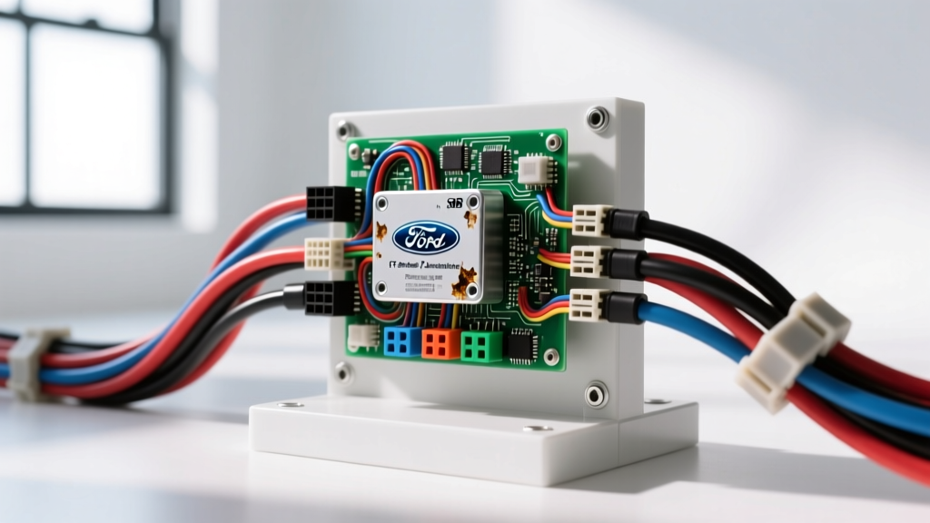
The Architecture of Modern F-150 Electrical Faults
When diagnosing late-model Ford F-150 electrical problems, technicians must abandon legacy 12V point-to-point troubleshooting paradigms. The modern F-150 relies on a highly multiplexed network topology governed by the Body Control Module (BCM) and the Smart Junction Box (SJB). Consequently, what appears to be a simple lighting or accessory failure is frequently a symptom of a High-Speed Controller Area Network (HS-CAN) topology fault, Local Interconnect Network (LIN) bus degradation, or severe galvanic corrosion at critical grounding nodes. This advanced technical deep dive dissects the most complex Ford F-150 electrical problems, focusing on SJB water ingress, CAN bus differential signaling anomalies, and high-current ground degradation protocols.
Symptom-to-Subsystem Decision Matrix
Before connecting a multimeter or oscilloscope, map the customer concern to the affected network domain. Random, seemingly unrelated electrical glitches usually indicate a network-level failure rather than individual component faults.
| Primary Symptom | Secondary Symptom | Probable Subsystem / Network | Diagnostic Starting Point |
|---|---|---|---|
| Instrument cluster reset | U-codes in BCM / PCM | HS-CAN Bus Topology | OBD-II DLC Pins 6 & 14 |
| Right-side lighting failure | Battery parasitic drain | SJB Internal / C2280 Connectors | Passenger Kick Panel SJB |
| Power window inoperative | Door lock actuator chatter | LIN Bus (Door Module) | Driver Door A-Pillar Boot |
| Starter relay no-crank | PCM communication loss | Ground G101 / PCM Power Relay | Engine Bay Ground Stud |
Deep Dive: Smart Junction Box (SJB) Internal Corrosion
The Smart Junction Box, located behind the right front kick panel and A-pillar trim, is the central routing hub for the F-150s chassis and body wiring. A pervasive cause of severe Ford F-150 electrical problems in the 2015-2020 generation is water ingress into the SJB. This typically occurs due to clogged cowl drains or compromised sunroof drain tubes, allowing water to travel down the A-pillar and pool inside the C2280 series connectors.
Pinout and Wire Color Verification (C2280B Connector)
When inspecting the SJB, technicians must verify the integrity of the 40-pin C2280B connector. Look for green/white copper oxide buildup on the male and female terminals. Below is a critical reference for the primary power and network feeds within this connector.
| Pin Number | Wire Color | AWG Size | Circuit Function |
|---|---|---|---|
| Pin 1 | Yellow/Green | 10 AWG | Battery Hot Feed (B+) |
| Pin 6 | White/Blue | 20 AWG | HS-CAN High (+) |
| Pin 14 | White | 20 AWG | HS-CAN Low (-) |
| Pin 22 | Black/Yellow | 14 AWG | Chassis Ground (G206) |
| Pin 35 | White/Red | 18 AWG | Run/Start Relay Feed |
Diagnostic Protocol: If corrosion is present on the 20 AWG CAN bus pins (6 and 14), the differential voltage will skew, causing the transceivers to flag a 'Bus Off' state. Do not attempt to clean severe corrosion with electrical contact cleaner alone; the terminal tension is permanently compromised. The affected pigtail must be spliced using OEM-approved crimp-and-seal heat shrink connectors to maintain the twisted pair geometry and prevent future moisture intrusion.
Advanced CAN Bus Diagnostics: Terminating Resistors and Voltage Drops
The HS-CAN network operates using differential signaling to achieve high common-mode rejection, which is vital in the high-EMI environment of a modern truck bed and engine bay. According to SAE J2284-4 standards for high-speed CAN, the network requires two 120-ohm terminating resistors placed at the physical ends of the bus topology to prevent signal reflection.
Step-by-Step Oscilloscope and Multimeter Verification
- Static Resistance Test: Disconnect the negative battery cable to ensure all modules are asleep. Measure resistance across OBD-II DLC Pin 6 (CAN-H) and Pin 14 (CAN-L). A healthy F-150 HS-CAN network will read exactly 60 ohms (two 120-ohm resistors in parallel). A reading of 120 ohms indicates one open terminating resistor (often inside the PCM or IPC). A reading of infinity indicates a complete network break.
- Dynamic Voltage Test: Reconnect the battery and turn the ignition to the 'ON' position. Using a digital multimeter, measure Pin 6 to chassis ground (should read ~2.6V) and Pin 14 to chassis ground (should read ~2.4V). The sum must equal approximately 5.0V.
- Oscilloscope Waveform Analysis: Connect a dual-channel scope to Pins 6 and 14. Set the timebase to 50µs/div. Observe the dominant and recessive states. During a dominant bit, CAN-H should rise to 3.5V while CAN-L drops to 1.5V, creating a 2.0V differential. If the waveforms exhibit excessive ringing or fail to mirror each other perfectly, inspect the twisted pair routing for separation. The twist rate must be maintained at approximately 1 twist per inch to preserve the SAE J1962 compliance and EMI shielding.
Ground Point G206 and G101 Degradation Protocol
Another major contributor to intermittent Ford F-150 electrical problems is the degradation of primary ground nodes. Ground G206, located on the right A-pillar beneath the SJB, handles the return paths for the right-side lighting, passenger window motors, and SJB logic. Ground G101, located in the engine compartment near the battery and Powertrain Control Module (PCM), handles high-current sensor returns and injector driver grounds.
Proper Voltage Drop Testing on High-Current Grounds
Resistance testing with a multimeter is insufficient for diagnosing ground faults under load, as a single strand of 12 AWG copper can show near-zero ohms but will fail to carry 30 amps without a massive voltage drop. Perform a dynamic voltage drop test instead:
- Set the multimeter to DC Volts.
- Place the red probe on the negative battery post (not the clamp, the actual lead post).
- Place the black probe on the clean metal grounding ring terminal of G206 or G101.
- Activate the load (e.g., command the passenger window motor or engage the starter).
- A healthy ground circuit will exhibit a voltage drop of less than 0.10V (100mV). A reading above 0.25V indicates severe galvanic corrosion between the copper ring terminal and the steel chassis stud.
Remediation: Remove the ground bolt. Clean the chassis mating surface with a brass wire brush until bare, shiny steel is exposed. Treat the bare metal with a zinc-rich anti-corrosion compound. Reinstall the ground ring terminal and torque the M6 stud to exactly 9 Nm (80 lb-in). Over-torquing will strip the sheet metal weld nut, while under-torquing will allow micro-movements that accelerate fretting corrosion.
Parasitic Draw and Module Sleep States
When diagnosing battery drain issues related to these electrical faults, technicians must understand the F-150s module sleep architecture. The SJB and BCM can take up to 40 minutes to enter 'deep sleep' mode after the ignition is turned off and the doors are locked. Breaking the battery connection to insert a multimeter in series will repeatedly wake the modules, leading to false parasitic draw readings. Instead, use a low-amp DC current clamp (such as the Fluke i410) around the negative battery cable. Wait for the 40-minute timeout. A normal resting draw should drop below 30mA. If the draw remains above 150mA, suspect a shorted LIN bus transceiver in a door module or a corroded SJB pin keeping the BCM awake via a spurious wake-up signal.
Authoritative References
For further diagnostic validation, technicians should consult the following standards and networks: