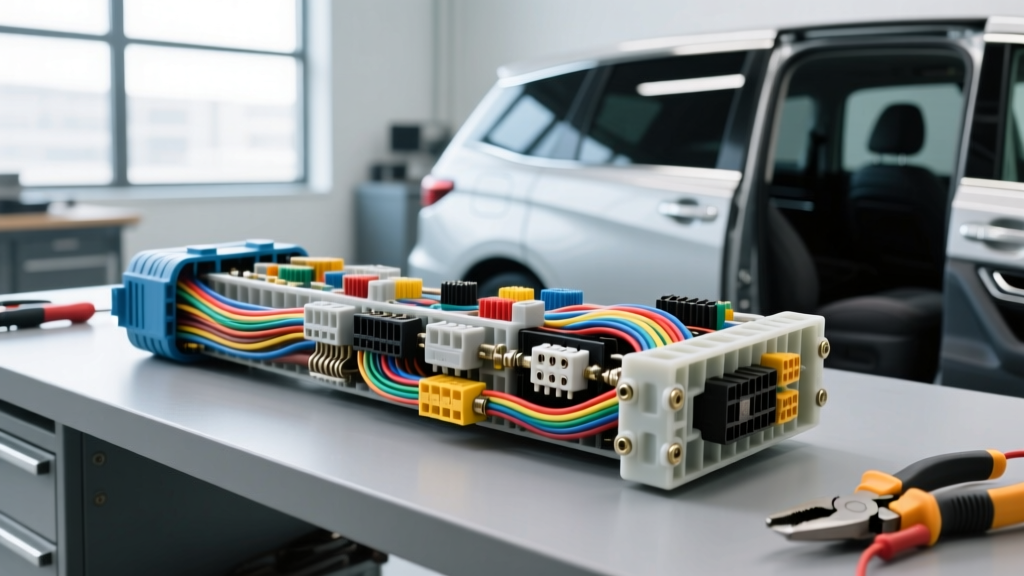
The Appeal and the Agony: Odysseys as Camper Platforms
The 2011–2017 (4th Generation) Honda Odyssey has become a legendary platform for overlanding and stealth camper conversions. Its robust 3.5L V6, spacious interior, and excellent payload capacity make it ideal for auxiliary battery setups, portable fridges, and high-wattage inverters. However, integrating aftermarket electrical systems into a modern, CAN-bus-heavy minivan frequently uncovers latent Honda Odyssey electrical problems. When planning a camper conversion, addressing these quirks early is the difference between a reliable off-grid rig and a stranded vehicle with a dead starter battery.
This guide approaches electrical troubleshooting from the perspective of an upgrade project. We will dissect the Multiplex Integrated Control System (MICU), dual-mode alternator behavior, and shared grounding issues that plague Odyssey camper builds, providing actionable wiring solutions and diagnostic flows.
The MICU Sleep-Mode Parasitic Drain
The most notorious of all Honda Odyssey electrical problems during camper builds is the parasitic drain caused by the Multiplex Integrated Control Unit (MICU). The MICU, located in the under-dash fuse box, manages body electronics and CAN-bus sleep states. When you tap into the wrong accessory circuit to power a DC-DC charger's ignition sense wire or an inverter's standby mode, you can inadvertently keep the MICU awake.
A sleeping Odyssey should draw less than 50 milliamps (mA) after the CAN-bus shuts down. However, if an aftermarket load pulls even 20mA from a retained-power circuit, the MICU may continuously wake the network, resulting in a parasitic draw of 400mA to 800mA. Over a weekend of camping, this will completely deplete the OEM 12V starter battery.
Troubleshooting the MICU Wake State
- Prepare the Multimeter: Set your digital multimeter (DMM) to the 10A DC setting and connect it in series with the negative battery terminal.
- Initiate Sleep Mode: Close all doors, the hood, and the tailgate. Ensure the key fob is at least 15 feet away from the vehicle to prevent the Smart Entry system from pinging.
- The 15-Minute Rule: Unlike older vehicles, the 4th Gen Odyssey requires 10 to 15 minutes for all modules to enter deep sleep. Do not open a door during this window, or the timer resets.
- Isolate the Circuit: If the draw remains above 50mA, begin pulling fuses from the under-dash MICU panel. Note: Pulling the 'Backup' or 'Intrusion Sensor' fuses is a common temporary fix for camper builders storing their rigs, but finding the offending aftermarket tap is the permanent solution.
The Dual-Mode Alternator Dilemma
Another major hurdle when solving Honda Odyssey electrical problems relates to the charging system. To meet fuel economy standards, Honda equipped these models with a dual-mode alternator. Under light cruising loads, the ECU commands the voltage regulator to drop output to 12.4V – 12.8V.
Camper conversions traditionally rely on Voltage Sensitive Relays (VSR) or simple isolators to charge the auxiliary house battery. A VSR typically engages at 13.3V and disengages at 12.8V. Because the Odyssey's alternator frequently drops below the VSR's engagement threshold, your auxiliary battery will rarely receive a full charge while driving, leading to premature sulfation of deep-cycle AGM or Lithium house batteries.
The Fix: DC-DC Smart Chargers
Abandon the VSR. Upgrade your wiring harness to accommodate a DC-DC smart charger (e.g., Victron Orion or Renogy DCC50S). A DC-DC charger utilizes an Ignition (IGN) signal wire to know when the engine is running, forcing it to pull available amperage regardless of the alternator's voltage fluctuations. You must tap the IGN sense wire into a true ignition-switched circuit, such as the 10A 'Day Light' fuse or the OBD2 Port Pin 16 (Battery) and Pin 4 (Chassis Ground) using a fused add-a-circuit, ensuring the MICU is not back-fed.
Technical Specifications: Aux Battery Isolation Wiring
When routing wires from the engine bay to the rear cargo area (where most camper auxiliary batteries reside), voltage drop over distance is a critical factor. The following table outlines the required specifications for a 15-foot cable run supporting a 40A DC-DC charger and a 1000W inverter.
| Circuit Function | Wire Gauge & Type | Color Code | Protection / Fuse | Termination / Connector |
|---|---|---|---|---|
| Main Battery to Isolator/Charger | 4 AWG OFC (Oxygen Free) | Red | 150A ANL Fuse (at battery) | 3/8" Ring Terminal, Heat Shrink |
| Isolator to Aux Battery (+) | 4 AWG OFC | Red | 150A ANL Fuse (at aux battery) | Quick-Disconnect Anderson Plug |
| Main Ground Return | 4 AWG OFC | Black | N/A | G101 Ground Block (Engine Bay) |
| DC-DC Ignition Sense Signal | 18 AWG GXL | Blue | 5A ATO Add-a-Circuit | Sumitomo Pigtail / Fuse Tap |
| Inverter Remote Switch | 22 AWG Twisted Pair | Yellow/Green | N/A | SPST Toggle with LED Indicator |
Shared Grounds and Power Sliding Door DTCs
A highly specific symptom of poorly executed camper wiring is the sudden failure of the power sliding doors or tailgate, accompanied by Diagnostic Trouble Codes (DTCs) like U0155 (Lost Communication with Instrument Panel Cluster) or B2088 (Tailgate Closer Unit Error).
Camper builders often ground heavy-draw inverters to the rear cargo area's sheet metal. Unfortunately, Honda utilizes shared ground points for the rear body control modules and the sliding door motors. Grounding a 1000W inverter (which can pull 85+ Amps at 12V) to a shared chassis point creates a massive voltage drop. This back-feeds resistance into the MICU's logic circuits, confusing the door control modules.
Proper Grounding Protocol
- Locate G503: This is the primary ground point in the rear hatch area. Never use this for high-amperage inverter grounds.
- Create a Dedicated Ground: Drill a new 5/16" hole in a structural, unpainted chassis rail near the auxiliary battery. Use a stainless steel bolt, a star washer to bite through the E-coat, and apply dielectric grease over the termination to prevent corrosion.
- Verify Voltage Drop: With the inverter under a 500W load, measure the voltage drop between the inverter's negative terminal and the negative terminal of the auxiliary battery. It should read less than 0.10V DC. Anything higher indicates inadequate grounding or undersized wire.
Upgrade Troubleshooting Decision Tree
Use this logical flow when diagnosing post-modification electrical gremlins in your Odyssey camper build:
- Symptom: Starter battery is dead after 2 days of camping, but auxiliary battery is full.
- Check 1: Is the DC-DC charger's standby current drawing from the starter battery? (Fix: Ensure charger has auto-isolation or install a battery disconnect switch).
- Check 2: Is the MICU asleep? (Fix: Perform the 15-minute parasitic draw test outlined above).
- Symptom: Inverter shuts down under heavy load (e.g., microwave), but auxiliary battery shows 12.6V at the posts.
- Check 1: Measure voltage directly at the inverter's input terminals under load. If it drops below 10.5V, you have severe voltage drop in the 4 AWG wiring or a crimp failure.
- Check 2: Check the ANL fuse connections for heat. Loose set-screws on ANL blocks cause resistance and thermal shutdowns.
Authoritative References
For deeper wiring diagrams and factory service manual (FSM) pinouts, consult the following resources:
- Honda TechInfo Portal - Official factory service manuals and MICU circuit diagrams.
- OdyClub Forums - The definitive community resource for 4th-Gen Odyssey camper builds and alternator wiring schematics.
- SAE J1284 Standard - Specifications for blade-type fuses and circuit protection in automotive auxiliary wiring.