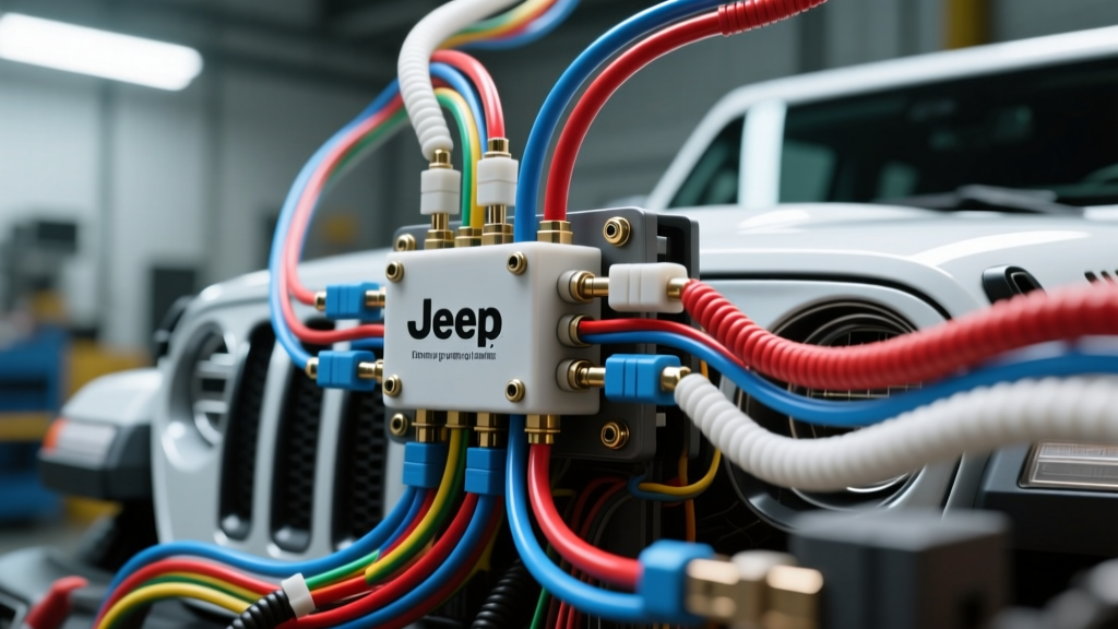
The Myth of the Automotive Curse: Science Over Superstition
When your dashboard lights up like a Christmas tree, the fuel pump relay clicks erratically, and the engine stalls at random intervals, it is incredibly common for frustrated owners to joke about the spiritual meaning of electrical problems. Enthusiasts and DIY mechanics often refer to the "gremlins" or a "curse" haunting their vehicle, especially when dealing with notoriously complex platforms like the Jeep Wrangler JK (2007–2018). But in the realm of professional automotive diagnostics, there are no ghosts, poltergeists, or bad omens. There is only physics, oxidation, thermal expansion, and human error.
Searching for the spiritual meaning of electrical problems is usually a symptom of diagnostic fatigue. When intermittent faults defy basic visual inspection, the human brain naturally seeks a supernatural explanation for what is actually a microscopic fracture in a solder joint or a corroded ring terminal. This guide exorcises these myths by replacing superstition with systematic voltage drop testing, Controller Area Network (CAN) bus analysis, and strict safety protocols. We will focus heavily on the common mistakes and critical safety warnings that turn manageable wiring issues into seemingly "cursed" nightmares.
Common Mistake #1: Ignoring the "Holy Trinity" of Ground Points
The most frequent cause of so-called ghost electrical issues is a misunderstanding of ground circuit integrity. In the Jeep Wrangler JK, the G100 (left inner fender), G200 (right inner fender), and G300 (engine block) ground points are the lifeblood of the Powertrain Control Module (PCM) and the Totally Integrated Power Module (TIPM).
The Missing Star Washer Error
A massive mistake DIYers make when performing engine work or aftermarket lighting installs is reattaching the 10 AWG black ground wires to painted surfaces or omitting the serrated star washer. The star washer is designed to bite through the zinc coating and paint to establish bare metal-to-metal contact. Without it, the circuit relies on the conductivity of the paint and primer, which act as resistors. According to Ohm's Law (V = I x R), even a slight increase in resistance (R) on a high-amperage ground will result in a massive voltage drop (V). This causes the PCM to see erratic sensor data, triggering random Check Engine Lights (CELs) and harsh transmission shifts that owners often attribute to a "cursed" vehicle.
Common Mistake #2: Backprobing the CAN C Bus Incorrectly
Modern vehicles communicate via the CAN C bus, a high-speed twisted pair network operating at 500 kbps. When diagnosing a U0100 (Lost Communication with ECM) code, many amateurs attempt to backprobe the Data Link Connector (DLC) using thick, standard multimeter probes.
- DLC Pin 6: CAN C Bus (+) - Typically White or Dark Green wire.
- DLC Pin 14: CAN C Bus (-) - Typically White/Black or Dark Green/Orange wire.
The Mistake: Forcing a thick probe into the rear of the OBD2 connector spreads the delicate female terminal tangs. This permanently ruins the terminal's tension, leading to an intermittent connection that vibrates loose while driving. This creates a "ghost" communication fault that only happens when hitting bumps, reinforcing the myth of the spiritual meaning of electrical problems. Always use dedicated, ultra-thin backprobing pins or T-pin adapters when measuring CAN bus waveforms with an oscilloscope or Digital Multimeter (DMM).
Critical Safety Warnings: When "Spiritual" Fixes Become Deadly
Attempting to bypass or "exorcise" electrical faults without understanding the underlying safety architecture can lead to catastrophic vehicle fires or fatal airbag deployments.
Warning 1: The Airbag (SIR) Circuit Taboo
The Supplemental Inflatable Restraint (SIR) system, commonly known as the airbag circuit, is identifiable by its bright yellow connectors and yellow conduit wrapping. A common and incredibly dangerous mistake is using a standard DMM to test continuity across the clockspring or squib circuits. Standard multimeters output a small voltage to measure resistance; this voltage is more than enough to inadvertently trigger the pyrotechnic charge in an airbag module, causing it to deploy in your face. Furthermore, never attempt to repair a frayed yellow SIR wire with standard solder and heat shrink. SAE standards dictate that SIR wiring must be replaced as a complete harness assembly or repaired using manufacturer-approved, ultrasonically welded splice kits.
Warning 2: Bypassing the TIPM Fuel Pump Relay
The Jeep JK TIPM is notorious for internal solder joint fractures on the fuel pump relay circuit (C1 Connector, Pin 12). When the fuel pump stops receiving 12V, desperate owners sometimes wire a "ghetto fix" by running a fused jumper wire directly from the battery to the fuel pump harness. Do not do this. Bypassing the TIPM removes the PCM's ability to cut fuel pressure in the event of a rollover or collision, turning a minor accident into an inferno. The correct, safe repair involves installing an external, ISO-standard 30A relay harness specifically designed to draw load directly from the battery while still utilizing the PCM's low-side trigger signal for safe shutoff.
Symptom-Cause-Fix Decision Tree: Exorcising Intermittent Faults
Stop looking for the spiritual meaning of electrical problems and start following this systematic diagnostic decision tree to isolate the physical failure points.
Symptom: Random Stalling / Fuel Pump Loss
- Test: Connect a DMM to TIPM C1 Connector Pin 12 (Fuel Pump Output) and a known good chassis ground.
- Condition: Crank the engine. Observe voltage.
- Result A: 12.6V present, but pump doesn't run. Fix: Faulty fuel pump motor or corroded pump ground strap at the tank.
- Result B: 0V present, but fuel pump relay clicks. Fix: Internal TIPM solder fracture. Install external bypass relay kit.
- Result C: Voltage fluctuates between 4V and 11V. Fix: High resistance in the 14 AWG Pink/Light Green power feed wire. Perform a voltage drop test on the power side.
Symptom: Dim Headlights / Flickering Dash Cluster
- Test: Set DMM to DC Volts. Place the red probe on the alternator B+ terminal and the black probe on the battery positive post. Rev engine to 2000 RPM with headlights on.
- Result A: Reading is > 0.2V. Fix: High resistance in the main positive battery cable. Clean or replace the cable.
- Result B: Move black probe to the alternator case (bare metal). If voltage drop drops to < 0.05V, the alternator is grounded properly. If not, Fix: Clean the alternator mounting bracket mating surfaces.
- Result C: Check G100 ground strap. Place red probe on battery negative, black probe on the G100 ring terminal. Fix: If reading > 0.1V, remove G100, clean with a wire brush, reinstall with a new serrated star washer, and torque to 25 in-lbs.
Jeep Wrangler JK Electrical Specifications & Torque Chart
Adhering to manufacturer specifications is the ultimate defense against intermittent wiring faults. Use the following reference chart during your diagnostic and repair procedures.
| Component / Circuit | Wire Color / Gauge | Connector / Pin | Torque / Spec |
|---|---|---|---|
| G100 Ground (Left Fender) | 10 AWG Black | Ring Terminal to Chassis | 25 in-lbs (with star washer) |
| G200 Ground (Right Fender) | 10 AWG Black | Ring Terminal to Chassis | 25 in-lbs (with star washer) |
| Alternator B+ Output | 4 AWG Red | Stud Nut (8mm) | 85 in-lbs |
| CAN C Bus (+) | 20 AWG White | DLC Pin 6 | N/A (Tension check only) |
| CAN C Bus (-) | 20 AWG White/Black | DLC Pin 14 | N/A (Tension check only) |
| Fuel Pump Feed | 14 AWG Pink/Light Green | TIPM C1 Connector, Pin 12 | N/A |
| Battery Negative Cable | 2 AWG Black | Engine Block Stud | 120 in-lbs |
Advanced Parasitic Drain: The Shunt Method
If your battery dies every three days, your vehicle isn't "cursed"—it has a parasitic draw. A common mistake is pulling fuses one by one while watching the DMM, which wakes up the CAN bus modules every time the circuit is broken, rendering the test useless. Instead, use the shunt method. Connect your DMM in series (Amps mode) across the negative battery terminal and the disconnected negative cable. Use a jumper wire to maintain continuity while you wait for the modules to enter "sleep mode" (which can take up to 45 minutes on a Chrysler CAN network). Once asleep, remove the jumper wire. A normal sleep current should be under 50mA (0.05A). If it reads 1.5A, you likely have a stuck TIPM internal relay or a shorted aftermarket amplifier trigger wire.
Conclusion: Embracing the Laws of Physics
There is no spiritual meaning of electrical problems; there is only the relentless reality of Ohm's Law, Faraday's principles of induction, and the inevitable degradation of copper and solder. By abandoning superstitious thinking and embracing systematic voltage drop testing, proper terminal backprobing techniques, and strict adherence to safety protocols regarding SIR and high-current circuits, you can diagnose and repair even the most stubborn automotive gremlins. Arm yourself with a quality Digital Multimeter, a factory wiring diagram, and the patience to let the modules sleep, and you will find that every "curse" has a perfectly logical, scientific cure.